Radio communication apparatus and transfer rate decision method

a technology of transmission rate and communication apparatus, which is applied in the direction of frequency-division multiplex, wireless commuication services, instruments, etc., can solve the problems of inability to optimize the assignment of transmission rate, the reliability of information deteriorates, so as to achieve the optimization of transmission rate and high accuracy

Active Publication Date: 2005-06-16
INVT SPE LLC
View PDF8 Cites 51 Cited by
  • Summary
  • Abstract
  • Description
  • Claims
  • Application Information

AI Technical Summary

Benefits of technology

[0007] It is an object of the present invention to provide a radio communication apparatus and transmission rate determining method that enable determination of transmission rate to be optimized with high accuracy.

Problems solved by technology

However, in such determination of a transmission rate, there are following problems.
That is, even when a transmission rate is determined based on information of instantaneous moment, the reliability of the information deteriorates due to effects of delay in assignment, moving speed of a mobile station, and / or accuracy in measuring channel quality in the mobile station or base station.
However, when the moving speed is high (the Doppler frequency is large), propagation environments vary greatly, and the reliability of the information deteriorates.
As a result, it is not possible to optimize the assignment of transmission rate, and there arise a possibility of having a significant effect on the throughput.
In addition, such an issue is not limited to HSDPA as described above, and arises widely in systems for controlling the transmission rate.
In other words, although the spreading factor is fixed in HSDPA, since determination of the transmission rate is also related to the spreading factor and transmission power in addition to the modulation scheme and coding rate, it is not possible to optimize the determination of transmission rate when reliabilities of the above-mentioned pieces of information deteriorate, and there arises the possibility of having a significant effect on performance of the transmission system.

Method used


Image

  • Radio communication apparatus and transfer rate decision method
  • Radio communication apparatus and transfer rate decision method
  • Radio communication apparatus and transfer rate decision method

Examples


first embodiment

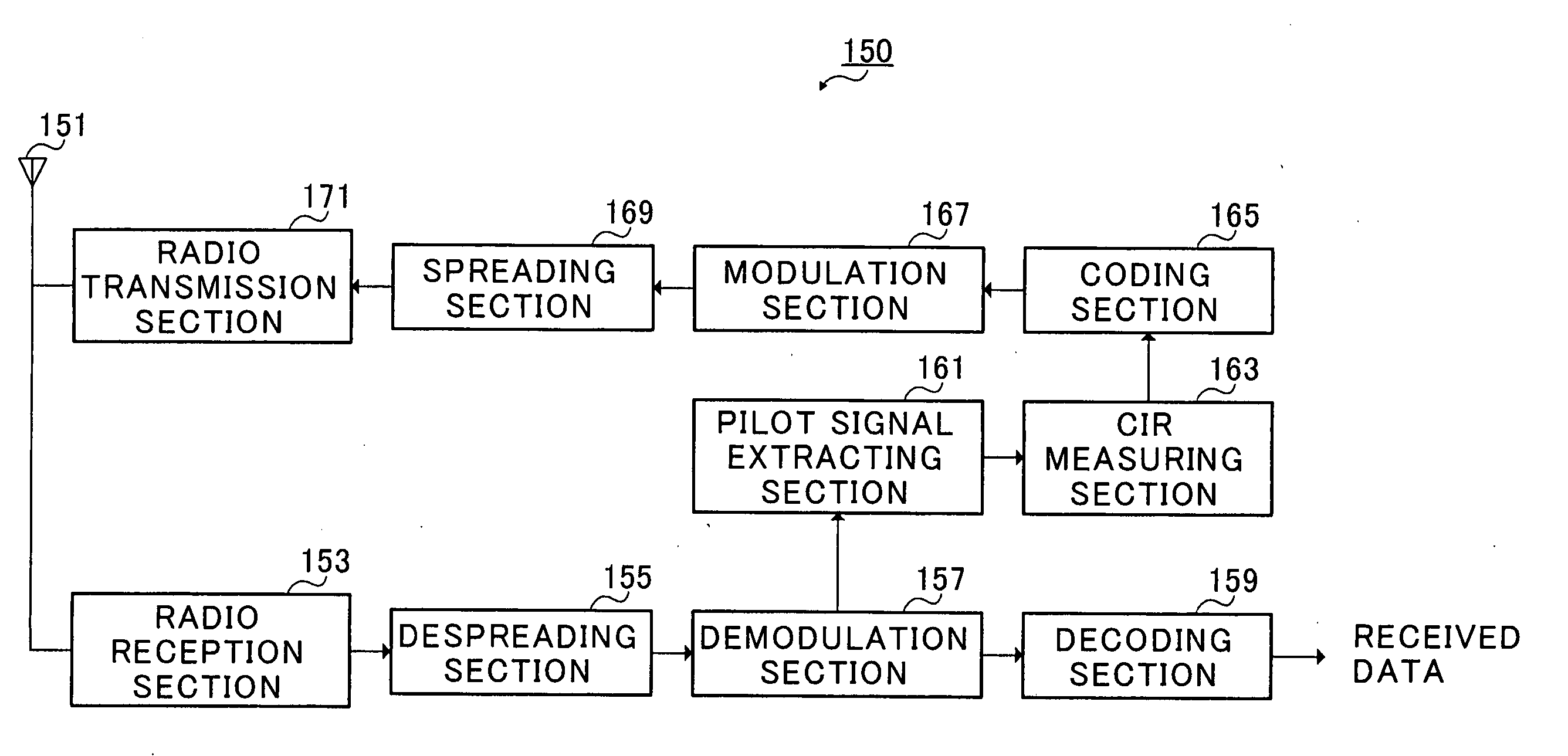
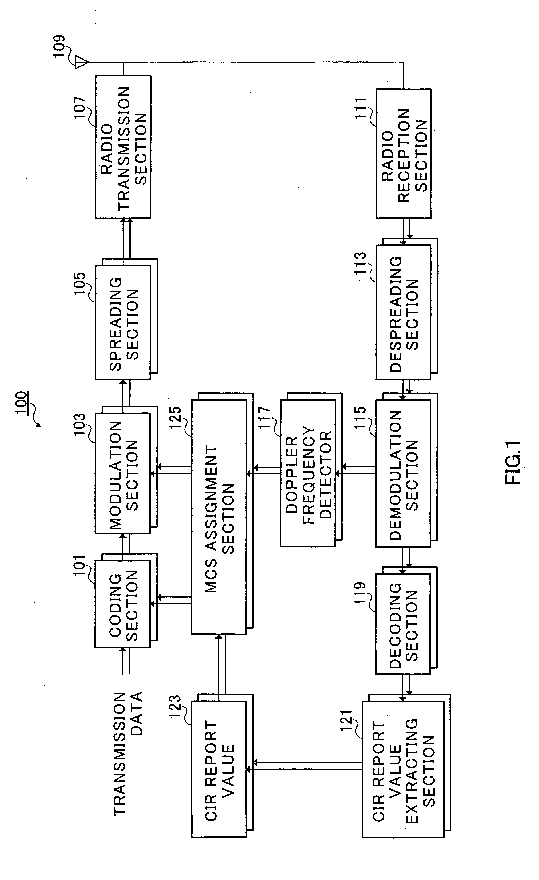
[0034]FIG. 1 is a block diagram illustrating a configuration of a radio communication apparatus on transmitting side according to the first embodiment of the present invention.

[0035] Radio communication apparatus 100 on transmitting as illustrated in FIG. 1 is, for example, a radio communication apparatus using the AMC technique, and has coding sections 101, modulation sections 103, spreading sections 105, radio transmission section 107, antenna 109, radio reception section 111, despreading sections 113, demodulation sections 115, Doppler frequency detectors 117, decoding sections 119, CIR report value extracting sections 121, CIR report value storing sections 123, and MCS assignment sections 125. Herein, in order to enable transmission data for a plurality of users to be handled, there are pluralities of sections as to 101, 103, 105, 113, 115, 117, 119, 121, 123 and 135, except radio transmission section 107, antenna 109 and radio reception section 111. Radio communication apparat...

second embodiment

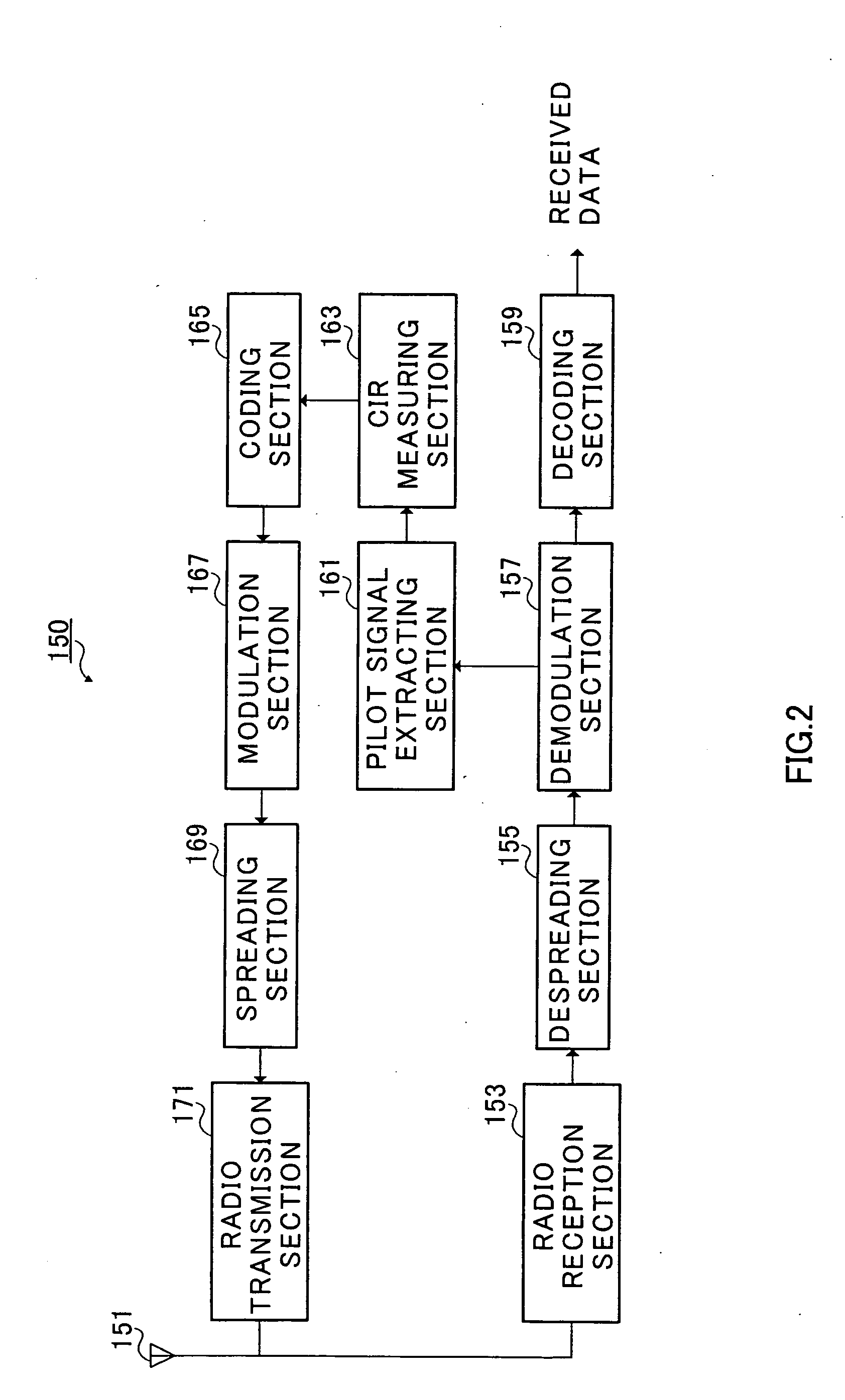
[0062]FIG. 5 is a block diagram illustrating a configuration of a radio communication apparatus on transmitting side according to the second embodiment of the present invention. In addition, radio communication apparatus 200 (base station) on transmitting side has basically the same configuration as that of radio communication apparatus 100 (base station) on transmitting side as illustrated in FIG. 1, and therefore, the same structural elements are assigned the same reference numerals to omit the descriptions. Further, a radio communication apparatus (mobile station) on receiving side that performs ratio communications with radio communication apparatus 200 (base station) on transmitting side has the same configuration as that of radio communication apparatus 150 (mobile station) on receiving side as illustrated in FIG. 2, and the descriptions thereof are omitted.

[0063] It is a feature of this embodiment to correct the relational expression of MCS (coding rate and modulation scheme...

third embodiment

[0067]FIG. 6 is a block diagram illustrating a configuration of a radio communication apparatus on transmitting side according to the third embodiment of the present invention. In addition, radio communication apparatus 300 (base station) on transmitting side has basically the same configuration as that of radio communication apparatus 200 (base station) on transmitting side as illustrated in FIG. 2, and therefore, the same structural elements are assigned the same reference numerals to omit the descriptions. Further, a radio communication apparatus (mobile station) on receiving side that performs radio communications with radio communication apparatus 300 (base station) on transmitting side has the same configuration as that of radio communication apparatus 150 (mobile station) on receiving side as illustrated in FIG. 2, and the descriptions thereof are omitted.

[0068] It is a feature of this embodiment to directly correct the Doppler frequency (moving speed) of a mobile station us...


PUM


Abstract

A transmission rate determining method that enables assignment of transmission rate (modulation scheme and coding rate) to be optimized with high accuracy in the AMC technique. In the method, in abase station, Doppler frequency detector 117 detects the Doppler frequency (moving speed) of each mobile station. MCS assignment section 125 corrects a relational expression of MCS (coding rate and modulation scheme) and CIR based on the Doppler frequency (moving speed) obtained in Doppler frequency detector 117, for example, corrects a threshold in CIR, and determines MCS optimal for CIR report value. Results of assignment in MCS assignment section 125 are output to coding section 101 and modulation section 103.

Description

TECHNICAL FIELD [0001] The present invention relates to a radio communication apparatus and transmission rate determining method. BACKGROUND ART [0002] As a faster packet transmission system in IMT-2000, a system called HSDPA (High Speed Downlink Packet Access) has been studied for purposes of fast downlink peak transmission rate, low transmission delay, and high throughput, for example. As techniques for supporting HSDPA, a transmission system called AMC (Adaptive Modulation and coding) is disclosed in 3GPP (3rd Generation Partnership Project) TR25.848 “Physical layer aspects of UTRA High Speed Downlink Packet Access”. [0003] The AMC technique is to vary the modulation scheme and error correcting coding rate adaptively at high speed corresponding to variation in channel quality. In the AMC technique, as the channel quality is higher, a faster modulation scheme is used, thereby the error correcting coding rate is increased, and thus the transmission rate is increased. Specifically, ...

Claims


Application Information

Patent Timeline
Patent Type & Authority Applications(United States)
IPC IPC(8): H04W28/18H04W88/18
CPCH04W88/181H04W28/18
Inventor UEHARA, TOSHIYUKIMIYA, KAZUYUKIARIMA, TAKENOBUHIRAMATSU, KATSUHIKO
Owner INVT SPE LLC
Why Eureka
Try Eureka