

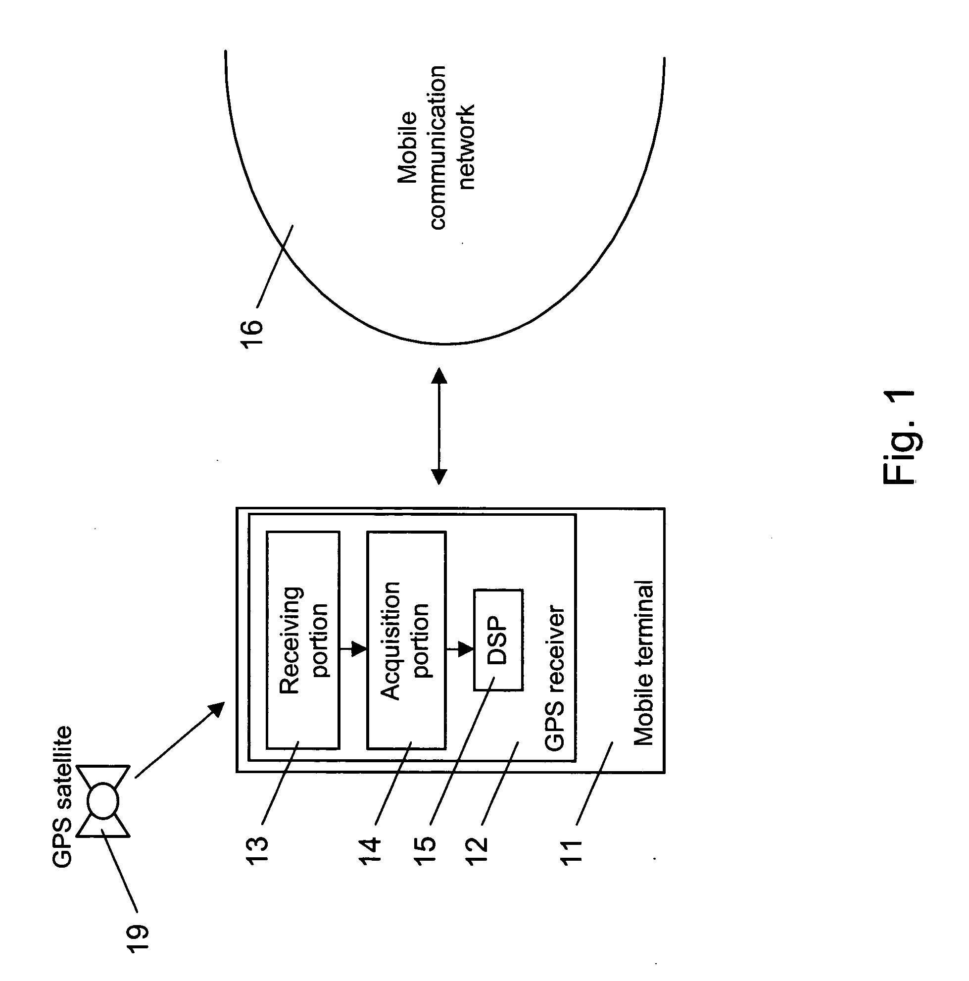
Acquisition of a code modulated signal
a code modulated signal and code technology, applied in the field of acquisition of code modulated signals, can solve problems such as significant complexity, and achieve the effects of reducing the complexity of massive acquisition engines, increasing the complexity of acquisition engines, and accelerating processing
- Summary
- Abstract
- Description
- Claims
- Application Information
AI Technical Summary
Benefits of technology
Problems solved by technology
Method used
Image

Examples
first embodiment
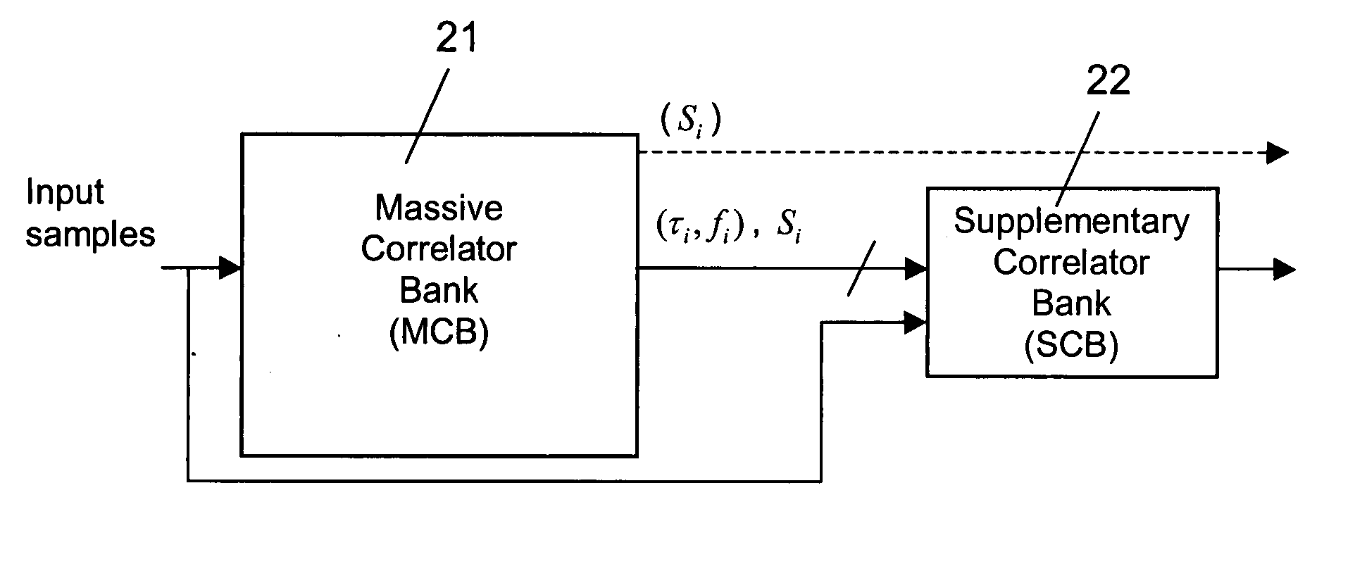
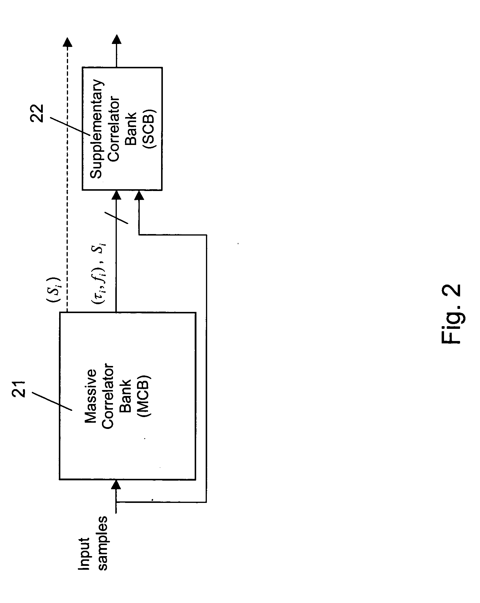
[0051]FIG. 4 is a schematic block diagram of a supplementary correlator bank 22 in the structure of FIG. 2.
[0052] The supplementary correlator bank 22 of FIG. 4 comprises a plurality of correlators 41. In each correlator 41, a sample input is connected via two subsequent multiplication elements 42, 43 and a multiplexer 44 to an integrating portion 45. Moreover, a code-phase indication input is connected to an input of a code generator 46. The output of the code generator 46 is connected to the first multiplication element 42. In addition, a frequency indication input is connected to an input of a carrier generator 47. The output of the carrier generator 47 is connected to the second multiplication element 43. Finally, an integration result input is connected to the multiplexer 44.
[0053] The operation of the supplementary correlator bank 22 of FIG. 4 is illustrated in the flow chart of FIG. 5.
[0054] The supplementary correlator bank 22 assigns each search option received from the m...
second embodiment
[0060]FIG. 6 is a schematic block diagram of a supplementary correlator bank 22 in the structure of FIG. 2.
[0061] The supplementary correlator bank 21 of FIG. 6 comprises again a plurality of correlators 61, of which only one is shown. In each correlator 61, a sample input is connected via two subsequent multiplication elements 62, 63 to an integrating portion 64. The integrating portion 64 is further connected via a portion 65 forming absolute or square values of input values and via a multiplexer 66 to a second integrating portion 67. Further, a code-phase indication input is connected to an input of a code generator 68. The output of the code generator 68 is connected to the first multiplication element 62. A frequency indication input is connected to an input of a carrier generator 69. The output of the carrier generator 69 is connected to the second multiplication element 63. Finally, an integration result input is connected to the multiplexer 66.
[0062] The operation of the su...
third embodiment
[0068]FIG. 8 is a schematic block diagram of a supplementary correlator bank in the structure of FIG. 2.
[0069] The supplementary correlator bank 21 of FIG. 8 comprises again a plurality of correlators 81, of which only one is shown. In each correlator 81, a sample input is connected via two subsequent multiplication elements 82, 83 to an integrating portion 84. The integrating portion 84 is further connected via a portion 85 forming absolute or square values of input values to a second integrating portion 86. Further, a code-phase indication input is connected to an input of a code generator 87. The output of the code generator 87 is connected to the first multiplication element 82. Moreover, a frequency indication input is connected to an input of a carrier generator 88. The output of the carrier generator 88 is connected to the second multiplication element 83.
[0070] The second integrating portion 86 is connected via an output of the correlator 81 to the DSP 15 of the GPS receive...
PUM
 Abstract
Description
Claims
Application Information