Radiographic apparatus

a technology of radiographic apparatus and x-ray radiographic apparatus, which is applied in the direction of tomography, material analysis using wave/particle radiation, instruments, etc., can solve the problems of sharp increase in data processing load, and excessive data processing load, so as to reduce the load of data processing

Inactive Publication Date: 2005-06-16
SHIMADZU CORP
View PDF4 Cites 6 Cited by
  • Summary
  • Abstract
  • Description
  • Claims
  • Application Information

AI Technical Summary

Benefits of technology

[0013] This invention has been made having regard to the state of the art noted above, and its object is to provide a radiographic apparatus for reducing a data processing load added as a result of a mechanical displacement occurring between an axis of revolution of a radiation emitting device and a three-dimensional radiation detecting device and an axis of radiation emission.

Problems solved by technology

However, the conventional X-ray radiographic apparatus has a problem of an excessive data processing load resulting from a mechanical displacement occurring between an axis of revolution RA of X-ray tube 51 and X-ray detector 52 and an axis of radiation emission XA.
The reconstruction process carried out based on X-ray image pixel data acquired in this state of displacement will result in errors due to the inclination of the axis of X-ray emission XA.
In such cases, however, the sophisticated algorithm incorporating complicated computing steps, or the data conversion performed beforehand for all of the X-ray image detection data, inevitably results in a sharp increase in the load of data processing.
This results in an inconvenience of not enabling an efficient calculating process to be performed by reading data to be used continuously at a time and temporarily storing the data in a cache memory providing a high-speed data transfer.

Method used


Image

  • Radiographic apparatus
  • Radiographic apparatus
  • Radiographic apparatus

Examples


Embodiment Construction

[0051] An embodiment of this invention will be described hereinafter with reference to the drawings.

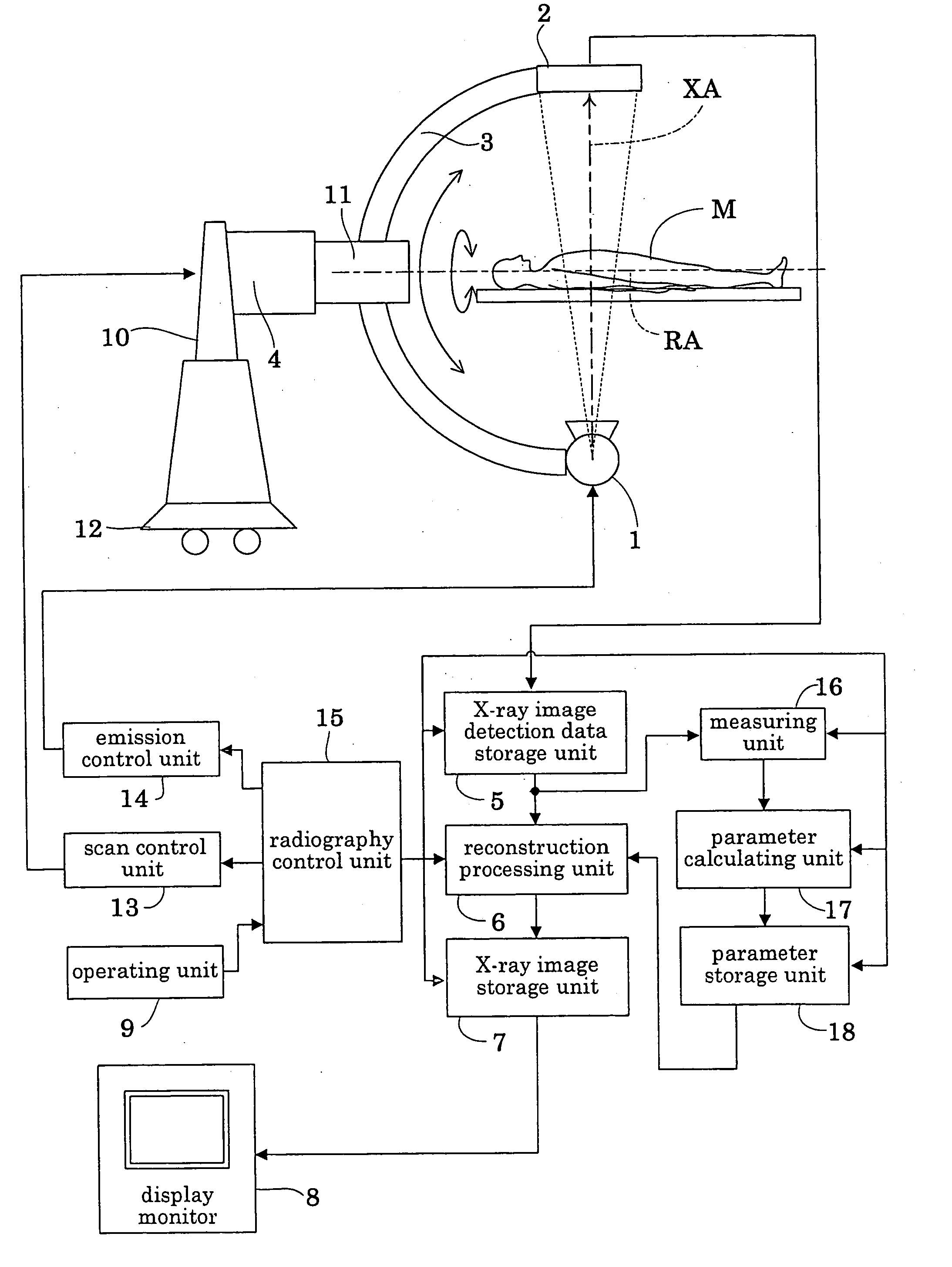
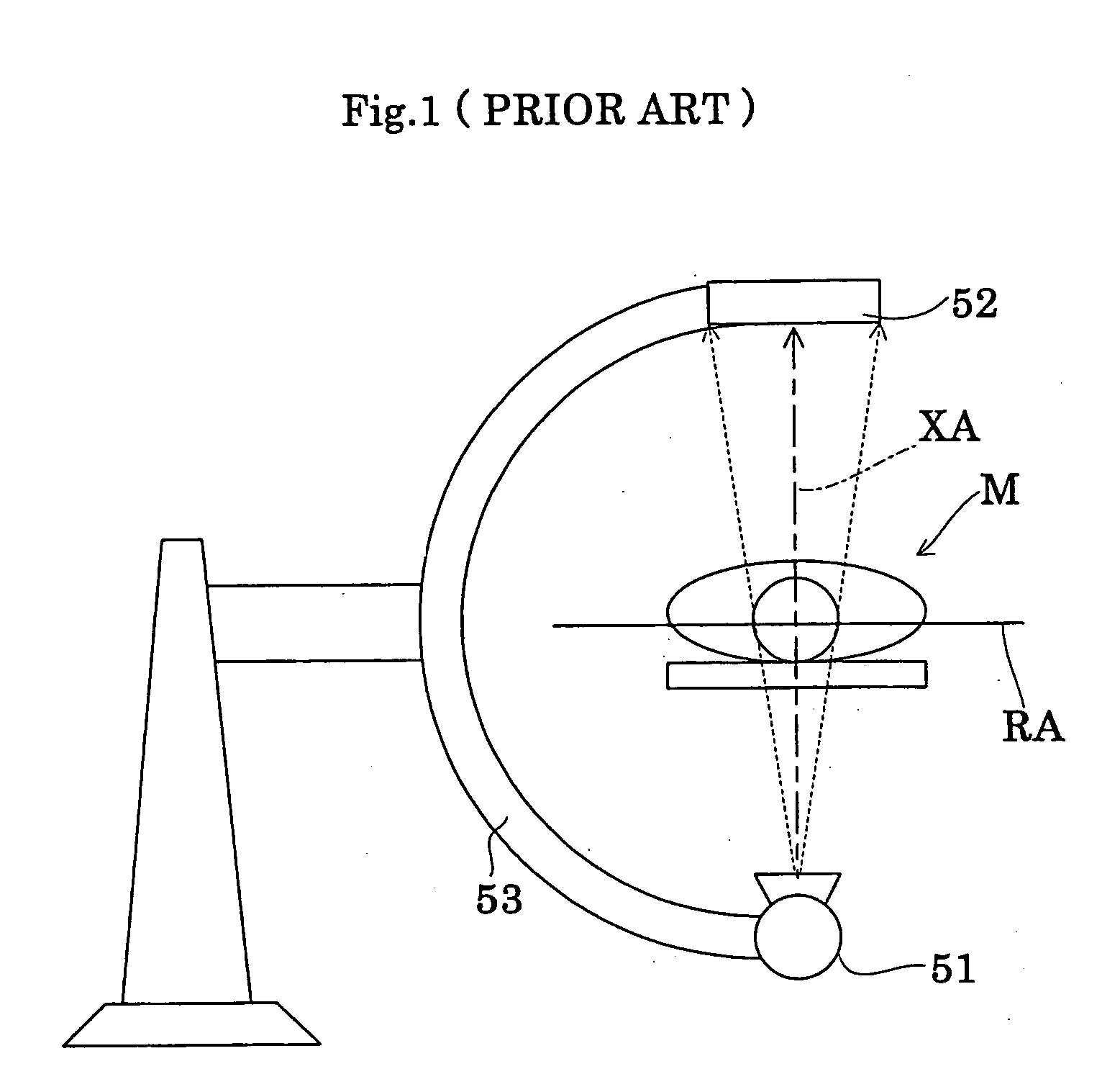
[0052] The apparatus in this embodiment is a C-shaped arm driving X-ray radiographic apparatus of the type that emits X rays in a cone-shaped beam, which is used in a medical institution such as a hospital. FIG. 4 is a block diagram showing an overall construction of the X-ray radiographic apparatus (hereinafter called simply “radiographic apparatus”). FIG. 5 is a schematic view showing a mechanical arrangement of an X-ray image pickup system in the apparatus according to this invention. The X-ray radiographic apparatus corresponds to the radiographic apparatus of this invention.

[0053] As shown in FIG. 4, the radiographic apparatus in this embodiment includes an X-ray tube 1 for emitting X rays in a cone-shaped beam, a flat panel type X-ray detector 2 (hereinafter called “FPD 2” where appropriate) for detecting transmitted X-ray images. The X-ray tube 1 and X-ray detector 2 are moun...


PUM

PropertyMeasurementUnit
spread angleaaaaaaaaaa
volumeaaaaaaaaaa
mechanical displacementaaaaaaaaaa

Abstract

A reconstruction process for processing pixel data for tomographic volume image data uses a concise reconstruction algorithm based on an assumption that an axis of X-ray emission axis always exists on a plane orthogonal to an axis of revolution of an X-ray tube and an FPD. In time of the reconstruction process, a corrected parameter is applied to the reconstruction algorithm for correcting a mechanical displacement occurring between the axis of revolution of the X-ray tube and FPD and the axis of X-ray emission. Thus, errors due to the mechanical displacement may be avoided by a simple data processing of setting the corrected parameter to the reconstruction algorithm, without impairing lightness of a data processing load on the reconstruction algorithm.

Description

BACKGROUND OF THE INVENTION [0001] (1). Field of the Invention [0002] This invention relates to a radiographic apparatus having a radiation emitting device for emitting radiation in a cone-shaped beam and a two-dimensional radiation detecting device for detecting transmitted radiation images. The radiation emitting device and radiation detecting device are revolvable about an axis of revolution provided by a straight line extending through an object under examination, for scanning a site of interest of the object. Pixel data for sectional images are put to a reconstruction process based on radiation image detection data outputted from the radiation detecting device in response to an emission of radiation in the cone-shaped beam, and on a reconstruction algorithm. More particularly, the invention relates to a technique for reducing a data processing load resulting from a mechanical displacement occurring between the axis of revolution of the radiation emitting device and radiation de...

Claims


Application Information

Patent Timeline
Patent Type & Authority Applications(United States)
IPC IPC(8): A61B6/03G06T11/00
CPCA61B6/032A61B6/4085A61B6/4233G06T11/005A61B6/4441A61B6/587A61B6/4405Y10S378/901A61B6/03
Inventor MORITA, HISANORI
Owner SHIMADZU CORP
Why Eureka
Try Eureka