Gas turbine high temperature turbine blade outer air seal assembly

a technology of outer air sealing and high temperature turbine blades, which is applied in the direction of machines/engines, liquid fuel engines, lighting and heating apparatus, etc., can solve the problems of significant distress of the turbine shroud assembly, the contact between the turbine shroud assembly and the blade tips of the rotor, and the failure of the turbine shroud components

Inactive Publication Date: 2005-06-16
HONEYWELL INT INC
View PDF18 Cites 132 Cited by
  • Summary
  • Abstract
  • Description
  • Claims
  • Application Information

AI Technical Summary

Problems solved by technology

During engine operation, exposure to the high temperature gas flow may result in failure of the turbine shroud components.
Due to the differing expansion of rotor and turbine shroud assembly components, it may also result in contact between the turbine shroud assembly and the blade tips of the rotor.
Turbine shroud assemblies have experienced significant distress due to a lack of robust sealing of the assembly.
This leakage may result in a significant reduction in the cooling cavity pressure (and back flow margin), which can result in hot gas ingestion and distress in the hardware.
If the back flow margin of the assembly becomes negative (or for some designs even a low positive number), hot flow path gas may ingest into portions of the shroud and may cause significant distress.
The challenge in maintaining good back flow margin is due to the difficulty in sealing the various leak paths that allow the cooling air to escape from the shroud cooling cavity.
Unfortunately, labyrinth seals are not suitable for some applications, and the metallic platform seals, which are secured in machined grooves in the sides of the segments, may fail in the operating environment of some engines.
In addition, assembly technicians may cut themselves on the small, sharp metallic platform seals.
Designs th

Method used


Image

  • Gas turbine high temperature turbine blade outer air seal assembly
  • Gas turbine high temperature turbine blade outer air seal assembly
  • Gas turbine high temperature turbine blade outer air seal assembly

Examples


Embodiment Construction

[0028] The following detailed description is of the best currently contemplated modes of carrying out the invention. The description is not to be taken in a limiting sense, but is made merely for the purpose of illustrating the general principles of the invention, since the scope of the invention is best defined by the appended claims.

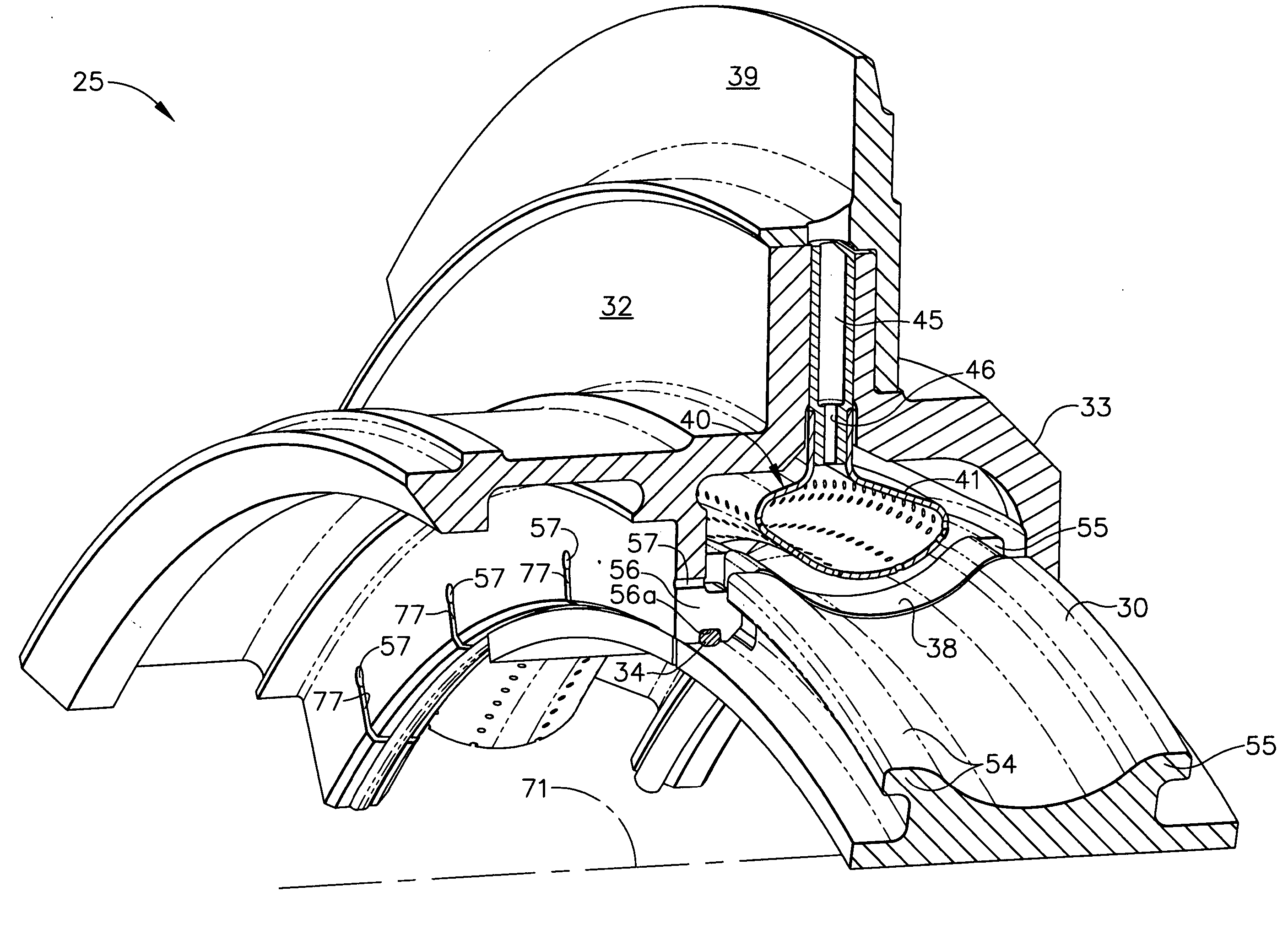
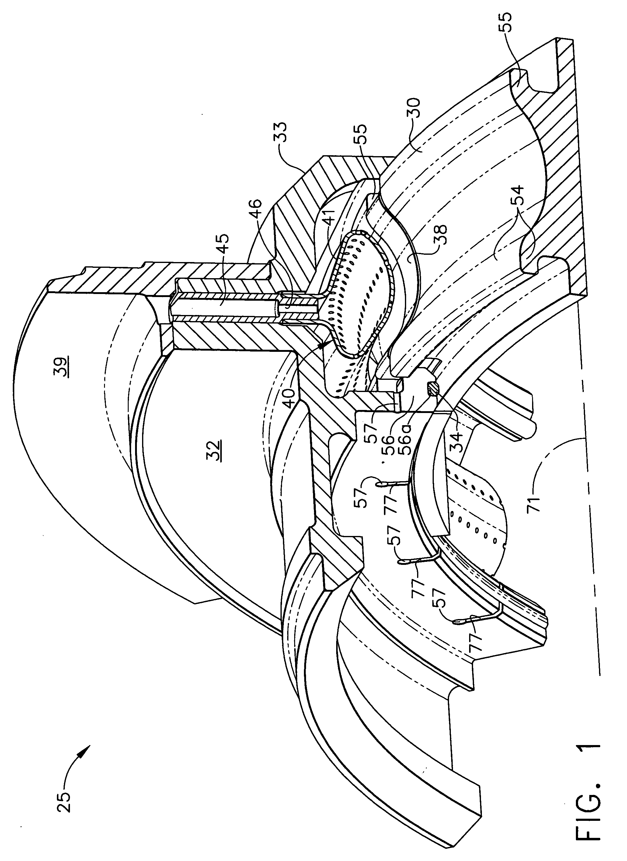
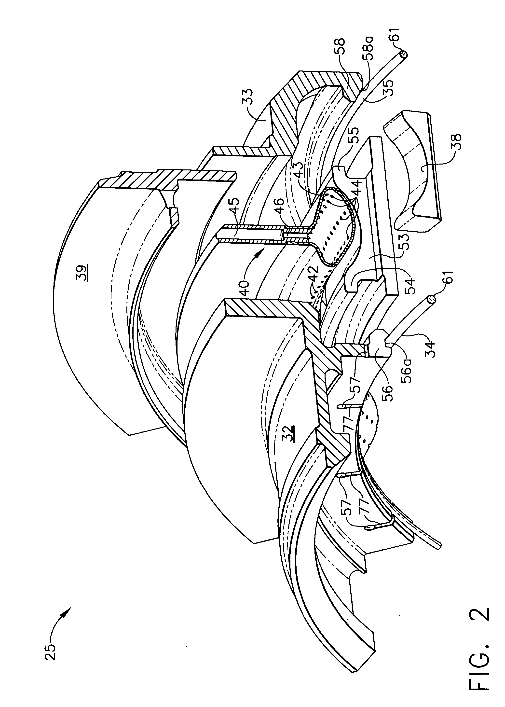
[0029] The present invention generally provides high pressure turbine (HPT) blade outer air seal (BOAS) assemblies, also known as turbine shroud assemblies and methods for producing the same. The turbine shroud assemblies produced according to the present invention may find beneficial use in many industries including aerospace and industrial. The turbine shroud assemblies of the present invention may be beneficial in applications including electricity generation, naval propulsion, pumping sets for gas and oil transmission, aircraft propulsion, automobile engines, and stationary power plants. This invention may be useful in any gas turbine application....


PUM

PropertyMeasurementUnit
Diameteraaaaaaaaaa
Areaaaaaaaaaaa

Abstract

A turbine shroud assembly includes forward and aft hangers, an axisymmetric plenum assembly, ceramic shroud segments, ceramic spacers, and forward and aft rope seals. The plenum assembly supplies impingement cooling to the shroud and the hangers. The impingement cooling to the forward and aft hangers is controlled independently to improve blade tip clearance. The rope seals are radially inward from the hangers and reduce cooling flow leakage. The turbine shroud assembly can operate in a higher temperature environment using less cooling flow than the prior art.

Description

GOVERNMENT INTERESTS [0001] The invention was made with Government support under contracts with the US Army (DAAJ02-94-C-0030), the US Air Force (F33615-94-C-2507) and the US Navy (N00019-94-C-0036). The Government has certain rights in this invention.BACKGROUND OF THE INVENTION [0002] The present invention generally relates to gas turbine engine systems and, more particularly, to high pressure turbine (HPT) blade outer air seal (BOAS) assemblies, also known as turbine shroud assemblies. [0003] Turbine shroud assemblies have been used extensively in gas turbine engines. The turbine shroud assembly may be positioned immediately downstream of an HPT nozzle. The turbine shroud assembly may surround a HPT rotor and may define an outer boundary of a high temperature gas flow path through the HPT. During engine operation, exposure to the high temperature gas flow may result in failure of the turbine shroud components. Due to the differing expansion of rotor and turbine shroud assembly com...

Claims


Application Information

Patent Timeline
IPC IPC(8): F01D9/04F01D11/00F01D25/12
CPCF01D9/04F01D9/042F01D11/005F01D25/12Y02T50/671Y02T50/676F05D2260/201F05D2300/2283F05D2230/90Y02T50/67Y02T50/60
Inventor MORRIS, MARK C.HALFMANN, STEVE H.WILSON, CRAIG A.POLLOCK, SHAWN J.LARSON, CARL A.
Owner HONEYWELL INT INC
Why Eureka
Try Eureka