Method of operating a fuel cell system

a fuel cell and fuel cell technology, applied in the field of apparatus and method of operating a fuel cell system, to achieve the effect of avoiding complications such as cooling systems with porous walls, lowering the freezing temperature of reaction products, and being less susceptible to freezing

Active Publication Date: 2005-06-16
GM GLOBAL TECH OPERATIONS LLC
View PDF2 Cites 7 Cited by
  • Summary
  • Abstract
  • Description
  • Claims
  • Application Information

AI Technical Summary

Benefits of technology

[0004] According to a first aspect of the invention, a method for the operation of a fuel cell system is disclosed. The method includes configuring at least one fuel cell within the system to include an anode, a cathode and a membrane disposed between the anode and the cathode. Additional steps include defining an operational sequence of the system to include a period of system activity wherein fuel (such as gaseous hydrogen) is reacted with oxygen (such as atmospheric oxygen) to produce electricity and at least one reaction product, arranging an infeed device to be in direct fluid communication with at least one of the anode and the cathode, and activating the infeed device upon generation of at least one temperature-based control signal. The infeed device is configured to selectively introduce a chemical compound into one or more parts of the system. The mixture of the chemical compound the reaction product lowers the reaction product's freezing temperature, making the reaction product (which can be, for example, water) less susceptible to freezing in cold weather during periods when the system is unable to generate enough heat, such as when the system is switched off. It will be appreciated by those skilled in the art that the fuel cell system can be made up from a plurality of individual fuel cells configured as a fuel cell stack. In the present context, the term “direct” in relation to fluid communication includes all instances of a defined, fluid-carrying flowpath (such as conduit), but does not include non-flowpath based modes, such as diffusion. Through this way of introducing the chemical compound, complications such as cooling systems with porous walls are avoided. In this way, the cooling system can be kept completely separate from the anode and the cathode of the fuel cell stack, thus reducing exposure of the anodes, cathodes and attendant catalysts to reaction-inhibiting chemicals. It will also be appreciated by those skilled in the art that the invention is valid generally for all fuel cell systems in which a gaseous fuel is used and water, a water-based mixture, or any other similarly freezable product arises as a reaction product.
[0008] The chemical compound introduced into the fuel cell system in a well distributed manner according to the present invention is advantageous in that the chemical compound enters into remote corners and related hollow spaces of the fuel cell components (such as the porous parts of the anode and cathode) so that water which is present in such hollow spaces mixes with the chemical compound to reduce the likelihood of freezing at the expected freezing temperatures of water. In this manner, the spaces remain free of ice so that the fuel cell system can be started up again at any time without having to go through an additional thawing step. Furthermore, the water which remains ensures that the fuel cell membranes remain moist, which is important to proper fuel cell operability.

Problems solved by technology

In addition, when the chemical compound is introduced by the infeed system during a shutdown sequence, it may displace the substantial entirety of fuel, oxygen or both that was present in the fuel cell during the period of activity just prior to the shutdown sequence.

Method used


Image

  • Method of operating a fuel cell system
  • Method of operating a fuel cell system
  • Method of operating a fuel cell system

Examples


Embodiment Construction

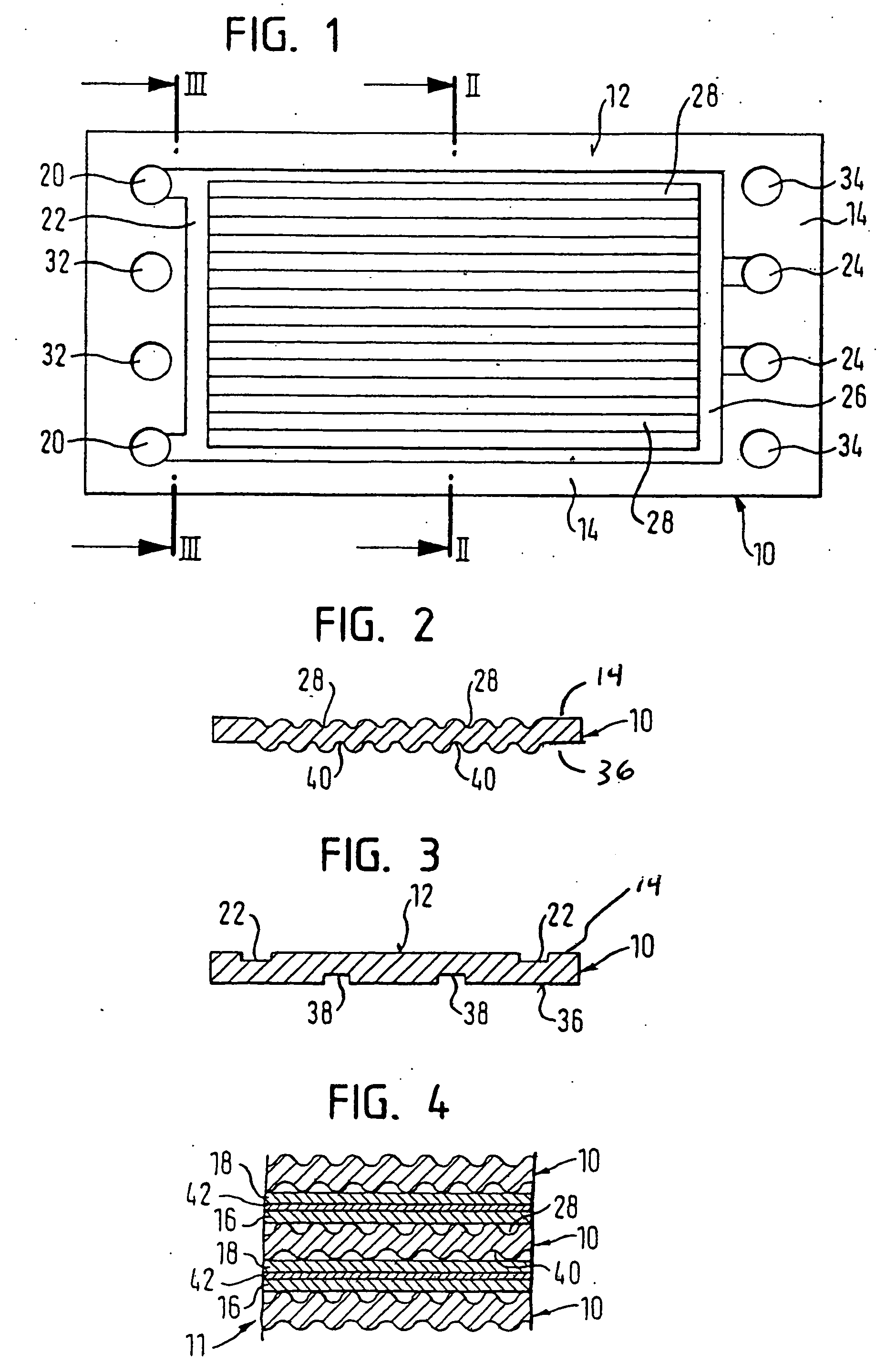
[0027] Referring first to FIGS. 1 and 3, features of a fuel cell are shown. Referring with particularity to FIG. 1, a bipolar plate 10 which is suitable for use in a fuel cell arrangement is shown. An upper surface 12 of the bipolar plate 10 is provided with a generally planar peripherally extending margin 14. Supply openings 20 for incoming oxygen (typically in the form of atmospheric air) are provided on one end of the bipolar plate 10 and are fluidly connected to a recessed channel 22 in the plate upper surface 12. Likewise, discharge openings 24 on the other end of the bipolar plate 10 are fluidly connected to a recessed channel 26. The shaping of the recessed channels 22, 26 in the bipolar plate 10 can be produced by conventional methods, such as through an etching process. The recessed channels 22, 26 are fluidly coupled to one another such that air introduced in supply openings 20 flows through recess channels 22, 26 to discharge openings 24 prior to being removed from the fu...


PUM

PropertyMeasurementUnit
boiling pointaaaaaaaaaa
freezing temperatureaaaaaaaaaa

Abstract

A method and apparatus for the operation of a fuel cell system to avoid the freezing of water resident in one or more fuel cells during periods of system inactivity. Each fuel cell includes at least an anode, a cathode and a membrane configured to establish electrolyte communication between reaction products formed at the anode and cathode. During fuel cell system operation, a portion of the water formed remains within the fuel cell; to avoid having the water freeze and inhibit subsequent system operation, a chemical compound introduced into the fuel cells mixes with the water still resident within the fuel cell to lower the temperature upon which the onset of water freezing occurs. The chemical compound can be introduced alone under pressure in the vapour phase, or in combination with the fuel, the incoming oxygen or an inert gas. In addition, system is configured such that the chemical compound can be introduced at numerous different locations.

Description

TECHNICAL FIELD [0001] The present invention relates generally to an apparatus and method of operating a fuel cell system, and more particularly to a fuel cell system wherein a chemical compound is selectively introduced into the system such that freezing of fuel cell reaction products is avoided. BACKGROUND OF THE INVENTION [0002] The interest in fuel cell systems is in its ascendancy, due in part to the ability of such systems to provide clean, reliable power for various applications that require the production of electricity or related useful power. In a typical fuel cell configuration, an electrolyte is sandwiched between electrodes (specifically, an anode and a cathode) such that positive ions generated at the anode flow through the electrolyte and react with ions generated at the cathode, while current generated by the flow of free electrons produced at the anode can be used to power one or more external devices. Some fuel cells require the presence of a catalyst material to p...

Claims


Application Information

Patent Timeline
Patent Type & Authority Applications(United States)
IPC IPC(8): H01M8/04007H01M8/04029H01M8/04089H01M8/04223
CPCH01M8/04007H01M8/04029Y02E60/50H01M8/04223H01M8/04253H01M8/04089H01M8/04228H01M8/04303H01M8/2483
Inventor BUSENBENDER, ILONA
Owner GM GLOBAL TECH OPERATIONS LLC
Why Eureka
Try Eureka