Method of detecting mismatching regions

a technology of mismatching region and detection method, which is applied in the identification of library members, organic chemistry, biochemistry apparatus and processes, etc., can solve the problems of noise, adversely affecting the detection accuracy, and not always being able to perform the reaction

Inactive Publication Date: 2005-06-16
FUJIFILM HLDG CORP +1
View PDF17 Cites 1 Cited by
  • Summary
  • Abstract
  • Description
  • Claims
  • Application Information

AI Technical Summary

Benefits of technology

[0030] With the method of detecting a mismatching region in accordance with the present invention, after the labeled polynucleotide, which has been labeled with the labeling substance, has been subjected to the hybridization with the plurality of the oligonucleotide probes, which have been fixed respectively to the plurality of regions on the supporting material, the first restriction enzyme is caused to act upon the single-stranded moiety of the labeled polynucleotide, which moiety has failed to form the double strand with each of the plurality of the oligonucleotide probes having been respectively fixed to the plurality of the regions on the supporting material. The first restriction enzyme is capable of decomposing the single-stranded polynucleotide from the terminal of the labeled polynucleotide. The single-stranded moiety of the labeled polynucleotide is thereby separated from the double strand, which has been formed by the labeled polynucleotide and each of the oligonucleotide probes. Thereafter, the signal, which is obtained from the labeling substance of the labeled polynucleotide, is detected with respect to each of the regions on the supporting material, and the first detection data is obtained from the signal detection. After the first detection data has been obtained, the second restriction enzyme is caused to act upon the mismatching moiety, at which the labeled polynucleotide and the certain oligonucleotide probe among the plurality of the oligonucleotide probes having been respectively fixed to the plurality of the regions on the supporting material have undergone the mismatch binding with each other. The second restriction enzyme is capable of cutting off the mismatching moiety. The mismatching moiety, at which the labeled polynucleotide and the certain oligonucleotide probe have undergone the mismatch binding with each other, is thereby separated from the region on the supporting material, to which region the mismatch polynucleotide has been bound. Thereafter, the signal, which is obtained from the labeling substance of the labeled polynucleotide, is detected with respect to each of the regions on the supporting material, and the second detection data is obtained from the signal detection. The first detection data and the second detection data are then compared with each other. Therefore, with the method of detecting a mismatching region in accordance with the present invention, the region on the supporting material, to which region the mismatch polynucleotide was bound, is capable of being specified and detected in accordance with the results of the comparison. Accordingly, for example, data obtained from the thus detected region is capable of being eliminated from data analysis. As a result, background noise due to the mismatch binding is capable of being suppressed, and the detection accuracy is capable of being enhanced.
[0031] Also, with respect to the oligonucleotide probe having been fixed to the region on the supporting material, to which region the mismatch polynucleotide was bound, there is possibility that a polymorph, which slightly varies in base sequence, e.g. a single base polymorph (SNP) in the cases of a gene, will be contained in the polynucleotide having been used as the target. Therefore, in cases where the region on the supporting material, to which region the mismatch polynucleotide was bound, is capable of being specified, an analysis is capable of being performed even further with respect to the oligonucleotide probe of the region having been specified, and the SNP, or the like, is thus capable of being detected. Further, detection of specific gene deletion becomes possible, depending upon the selection of the oligonucleotide probes to be fixed to the supporting material.

Problems solved by technology

However, it is not always possible to perform the reaction under the conditions optimum for each of the probe DNA's, which have been fixed respectively to the regions having been located at a high density.
The target DNA, which has undergone the mismatch binding, causes noise to occur at the time of signal detection and adversely affects a detection accuracy.
Therefore, the cDNA micro array has a high possibility that the probe DNA's on the cDNA micro array will under go the mismatch binding.
However, in both the cases of the oligonucleotide array and the synthetic oligo array, it is not always possible to design such that the mismatch binding does not occur.
Particularly, in cases where analysis is to be made with respect to a long gene, such as a cDNA, it is almost impossible to design such that the mismatch binding does not occur.
Specifically, under conditions of temperatures lower than the Tm value, background noise due to the mismatch binding increases.
Also, under conditions of temperatures higher than the Tm value, it becomes difficult for the polynucleotide to undergo the binding with the probes.
Furthermore, in order for the mismatch binding to be suppressed, fine adjustment for raising or lowering the salt concentration in a liquid subjected to reaction must be made, and considerable labor and time are thus required.
In cases where the hybridization is performed through adjustment of the pH value, the same problems as those described above arise.
As described above, in order for the mismatch binding during the hybridization to be suppressed, complicated adjustments must be performed, and considerable labor and time are required.
Also, new problems occur in that, depending upon the conditions for the suppression of the mismatch binding, perfect match binding, i.e. perfect complementary binding, is weakened.

Method used


Image

  • Method of detecting mismatching regions

Examples


Embodiment Construction

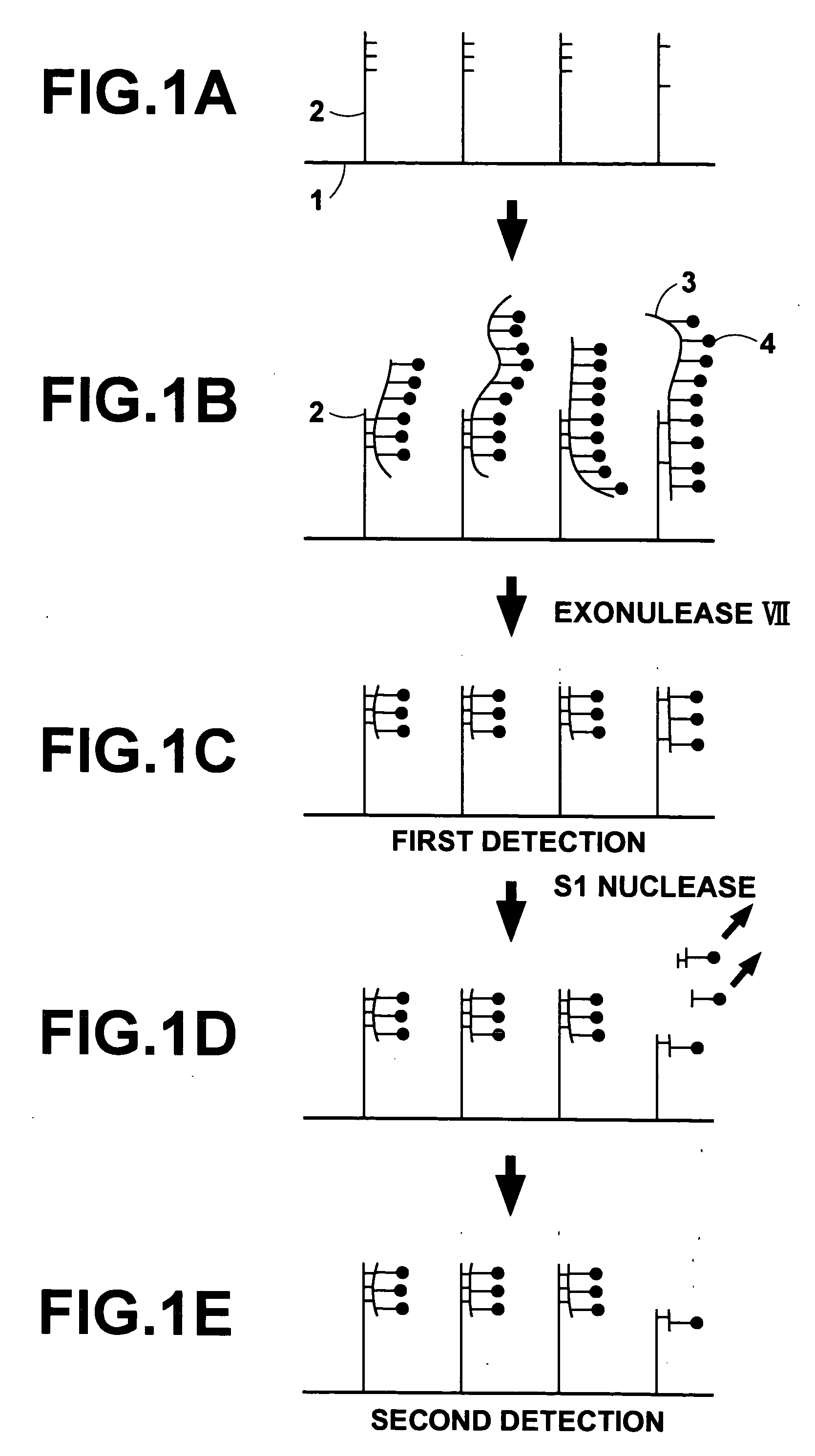
[0033] The present invention will hereinbelow be described in further detail with reference to the accompanying drawings.

[0034] An embodiment of the method of detecting a mismatching region in accordance with the present invention, wherein a DNA array comprising a supporting material and a plurality of oligo DNA probes having been fixed respectively to a plurality of regions on the supporting material is utilized, will be described hereinbelow. FIGS. 1A to 1E are explanatory views showing how a mismatching region is detected with an embodiment of the method of detecting a mismatching region in accordance with the present invention.

[0035] Firstly, a surface of a membrane filter 1 acting as a supporting material is processed such that carboxyl groups (COOH) or aldehyde groups (COH) are exposed from the surface of the membrane filter 1 to the exterior. Also, an amino group (NH2) is introduced into a 5′-terminal of each of synthetic oligo DNA's acting as DNA probes 2, 2, . . . Each of...


PUM

PropertyMeasurementUnit
temperatureaaaaaaaaaa
chemical luminescenceaaaaaaaaaa

Abstract

A labeled polynucleotide is subjected to hybridization with oligonucleotide probes fixed respectively to regions on a supporting material. With a first restriction enzyme, a single-stranded moiety of the labeled polynucleotide having failed to form a double strand with each probe is separated from a double strand having been formed by the labeled polynucleotide and each probe. First detection data is obtained from each region. A mismatching moiety, at which the labeled polynucleotide and a certain probe have undergone a mismatch binding, is separated with a second restriction enzyme, and second detection data is obtained from each region. The region to which the mismatch polynucleotide was bound is specified in accordance with results of a comparison between the first detection data and the second detection data.

Description

BACKGROUND OF THE INVENTION [0001] 1. Field of the Invention [0002] This invention relates to a method of detecting a mismatching region, in which a mismatch binding has occurred, on a biochemical analysis micro array used for detection, analysis, or the like, of a specific sequence contained in a polynucleotide, such as a DNA. [0003] 2. Description of the Related Art [0004] DNA micro arrays are expected to be applied to a wide range of fields of life science, such as monitoring of genetic expression, determination of base sequences of genes, analysis of gene polymorphism (SNP), analysis of gene amplification or deletion at cancered parts, classification of diseases, such as cancers, prediction of drug response characteristics, and searching of disease genes. [0005] Principles of assay techniques utilizing DNA micro arrays are based upon detection of nucleic acids through hybridization. Specifically, various different probe DNA's are arrayed at a high density at a plurality of regio...

Claims


Application Information

Patent Timeline
Patent Type & Authority Applications(United States)
IPC IPC(8): C12Q1/68C12P19/34
CPCC12Q1/6827C12Q1/6834C12Q2565/519C12Q2521/319C12Q2521/307
Inventor TSUCHIYA, TORU
Owner FUJIFILM HLDG CORP
Why Eureka
Try Eureka