Multiband starlight imaging photometer and detection method thereof
An imaging detector and multi-band technology, applied in the field of aerosol detection, can solve the problems such as the inability to provide night-time atmospheric aerosol limitations, etc.
- Summary
- Abstract
- Description
- Claims
- Application Information
AI Technical Summary
Problems solved by technology
Method used
Image
Examples
Embodiment 1
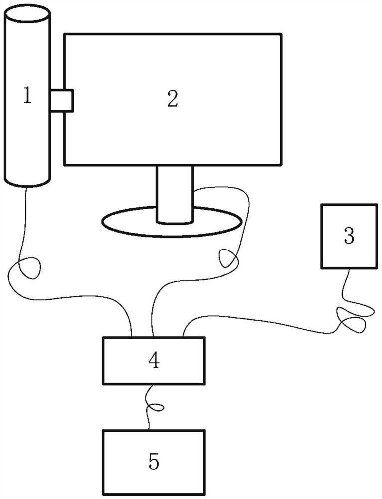
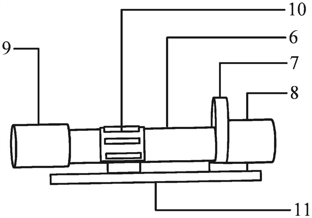
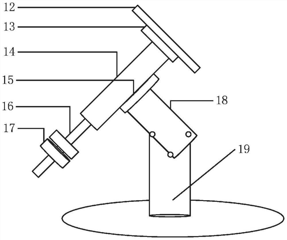
[0062] like Figure 7 As shown, according to the geographic location and time of the instrument, the computer 5 automatically selects a target star A suitable for local observation. Using the geographic location latitude, longitude, time, and meteorological parameters provided by the meteorological and GPS module 3, the computer 5 decides whether the weather conditions are suitable for observation. If it is suitable for observation, the computer 5 automatically calculates the right ascension and declination of the target star, and the computer 5 sends an instruction to track the turntable 2 two-dimensionally, so that the optical imaging detection system 1 points to the position of the target star, and after reaching the position, the filter wheel 7 is controlled to rotate, The target star is imaged on the CCD imaging detector 8 in sequence or by specifying the corresponding filter, and the collected image is downloaded to the computer 5. The computer 5 automatically filters th...
Embodiment 2
[0065] Based on Example 1, different target stars are observed alternately, such as Figure 8 , at the same time, select the target star A, target star B and target star C with different elevation angles (the number of target stars is optional), according to the geographical location and time of the instrument, use the geographical location provided by the meteorology and GPS module 3 The location latitude and longitude, time, and meteorological parameters are determined by the computer 5 whether the weather conditions are suitable for observation. If it is suitable for observation, the computer 5 automatically calculates the right ascension and declination of the target star A, and the computer 5 sends an instruction to track the turntable 2 two-dimensionally, so that the optical imaging detection system 1 points to the position of the target star A. After reaching the position, the filter wheel 7 is controlled. Rotate, sequentially or designate the corresponding filter, and ...
Embodiment 3
[0067] Based on Example 1, as Figure 9 As shown, in weather conditions with visible moonlight, select the moon as the light source for observation. The specific implementation is as follows: using the geographic location latitude, longitude, time, and meteorological parameters provided by the meteorological and GPS module 3, the computer 5 decides whether the weather conditions are suitable for observation. If it is suitable for observation, the computer 5 automatically calculates the right ascension and declination of the moon, and the computer 5 sends an instruction to track the turntable 2 in two dimensions, so that the optical imaging detection system 1 points to the moon. After the two-dimensional tracking turntable 2 reaches the position, it controls the filter wheel 7 to rotate. , and sequentially or designate the corresponding filter, the moon is imaged on the CCD imaging detector 8 in different wavelength bands, and the collected image is downloaded to the computer 5...
PUM
 Abstract
Description
Claims
Application Information
 - R&D
- Intellectual Property
- Life Sciences
- Materials
- Tech Scout
- Unparalleled Data Quality
- Higher Quality Content
- 60% Fewer Hallucinations
Browse by: Latest US Patents, China's latest patents, Technical Efficacy Thesaurus, Application Domain, Technology Topic, Popular Technical Reports.
© 2025 PatSnap. All rights reserved.Legal|Privacy policy|Modern Slavery Act Transparency Statement|Sitemap|About US| Contact US: help@patsnap.com


