Stent delivery system and method of use

a balloon dilation catheter and delivery system technology, applied in the field of balloon dilation catheters, can solve the problems of less than optimum steerability of the guidewire, difficulty in moving the guidewire with respect to the catheter, less than optimum torque control, etc., and achieve the effect of mitigating back bleeding

Inactive Publication Date: 2005-06-16
RICCI DONALD R
View PDF13 Cites 10 Cited by
  • Summary
  • Abstract
  • Description
  • Claims
  • Application Information

AI Technical Summary

Benefits of technology

[0052] Thus, the present inventor has discovered a balloon catheter which combines the advantages of the “over the wire” approach (i.e., optimum steerability, smoother movement of the guidewire with respect to the catheter (due to the coaxial relationship thereof), optimum torque control and the ability to exchange the guidewire while leaving the catheter in place) with the principal advantage of the “monorail” approach (i.e., rapid exchange of the balloon catheter with another balloon catheter while leaving the guidewire in place).
[0054] Thus, the present inventor has discovered a balloon dilation catheter which have one or more of the number of novel features. For example, it has been discovered that a particularly advantageous approach in facilitating guidewire removal from the catheter is to utilize materials for the tubular member which, when finely slitted, results in the longitudinal edges of the slit portion being abutting or touching engagement. This obviates or mitigates back bleeding through that portion of the catheter which is outside the patient during use. Another independently novel feature of the present balloon dilation catheter is the adapter located at the proximal end of the catheter. Specifically, the present inventor has discovered that the use of resilient valve in the adapter having a slit disposed therein (preferably aligned with the slit in the tubular member) allows for advantageous removal of the guidewire from balloon dilation catheter while obviating or mitigating unintended or accidental removal of the guidewire or damage thereto.

Problems solved by technology

The principal disadvantages of this approach include: less than optimum steerability of the guidewire, difficulties in moving the guidewire with respect to the catheter, less than optimum torque control and inability to exchange the guidewire while leaving the catheter in place.
The catheter illustrated by Horzewski has not gained widespread commercial popularity.
The principal is disadvantage of this approach is that exchange with another balloon catheter is relatively cumbersome (i.e., compared to the “monorail” approach discussed above.
The Schiffer catheter is disadvantageous since it requires the physician to execute two distinct and sequential steps to achieve “rapid exchange”.
Second, the physician must remove the catheter while the guidewire is held in position.
The requirement for these two distinct and sequential steps renders the Schiffer catheter cumbersome, time consuming and impractical to use.

Method used


Image

  • Stent delivery system and method of use
  • Stent delivery system and method of use
  • Stent delivery system and method of use

Examples


Embodiment Construction

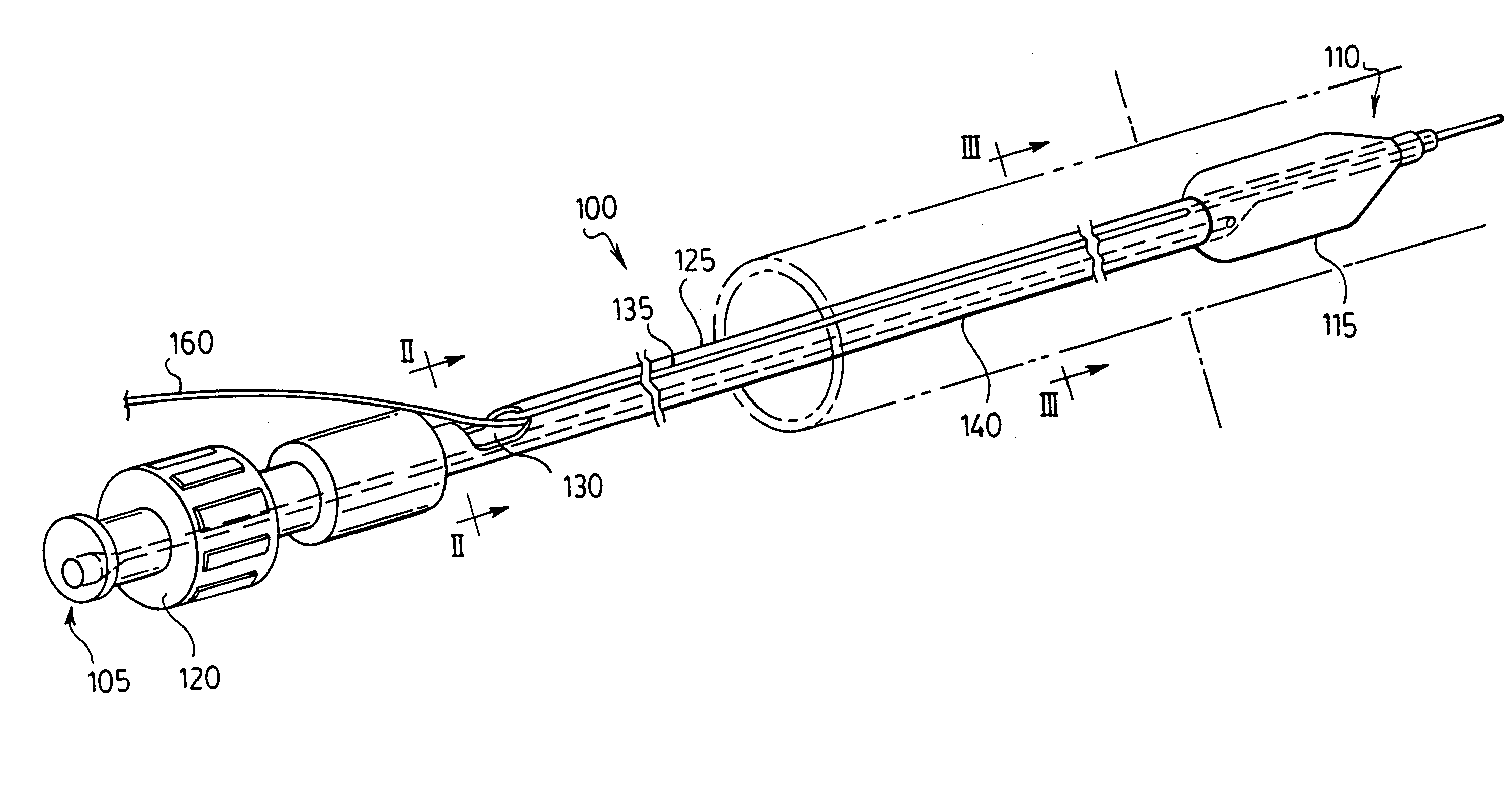
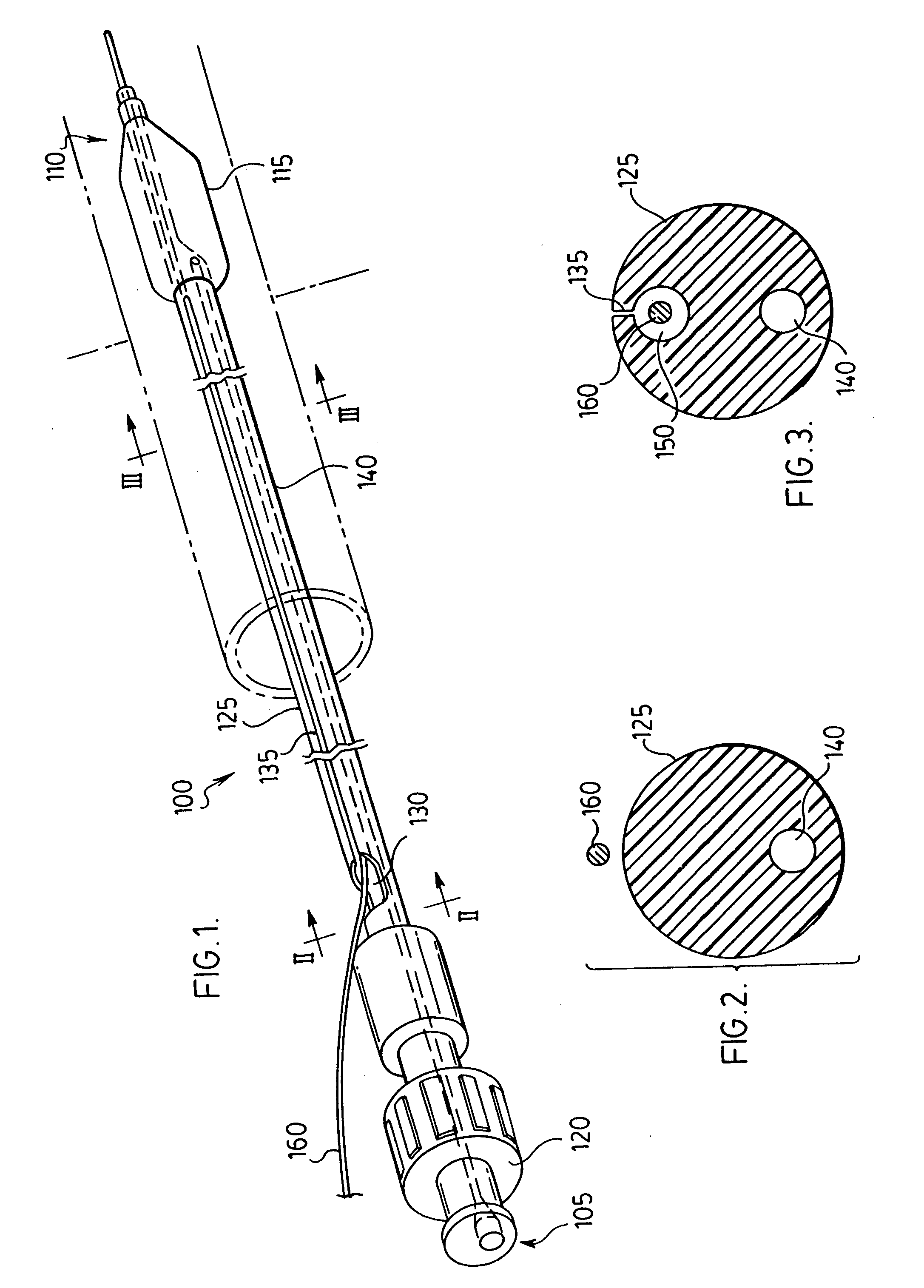
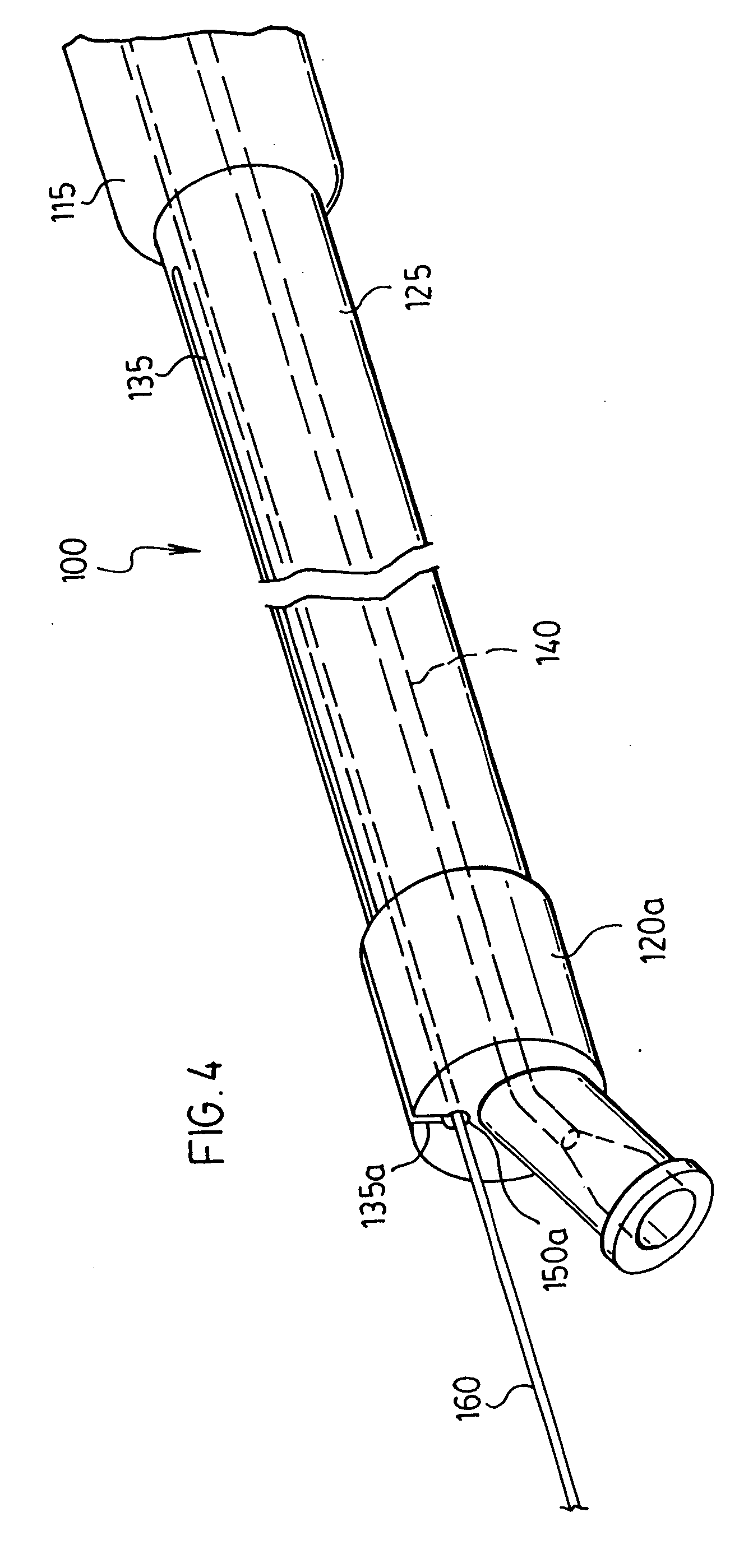
[0067] Thus, with reference to FIGS. 1-3, there is illustrated a balloon dilation catheter 100. Balloon dilation catheter 100 comprises a proximal end 105 and a distal end 110. Distal end 110 of balloon dilation catheter 100 comprises an expandable balloon 115. Proximal end 105 of balloon dilation catheter 100 comprises an single lumen Luer-type adaptor 120. Disposed between adaptor 120 and balloon 115 is a tubular member 125.

[0068] As will be apparent from FIG. 1, disposed in tubular member 125 is an opening 130. Also disposed in tubular member 125 is a slit 135 which extends from opening 130 to a point in tubular member 125 just proximal balloon 115.

[0069] With particular reference to FIGS. 2 and 3, tubular member 125 comprises a first lumen 140 and a second lumen 150. First lumen 140 is designed to be in communication with an interior of balloon 115. The design of the interface between balloon 115 and first lumen 140 is conventional—see for example Horzewski referred to hereina...


PUM


Abstract

A balloon dilation catheter comprising a tubular member having a proximal end and a distal end. An inflatable balloon is disposed at the distal end of the tubular member. A first lumen is disposed in the tubular member and in is communication with an interior of the inflatable balloon. A second lumen is disposed in the tubular member for receiving a guidewire substantially along a portion of its length. The second lumen has a first opening in the proximal region of the tubular member and a second opening at the distal region of the tubular member. A first slit is disposed longitudinally in the tubular member and extends along at least a portion of the tubular member, the first slit comprising a first pair of longitudinal edges in a side by side relationship. The tubular member is constructed of a resilient material such that, as the guidewire is separated from the second lumen, the longitudinal edges are biassed open from a first position to a second position having a gap greater than or equal a diameter of the guidewire. The subject balloon dilation catheter provides improved rapid exchange advantages of either the catheter or the guidewire used in a catheterization technique.

Description

BACKGROUND OF THE INVENTION [0001] 1. Field of the Invention [0002] In one of its aspects, the present invention relates to a balloon dilation catheter. In another of its aspects, the present invention relates to a catheterization method. [0003] 2. Brief Description of the Prior Art [0004] Balloon dilation catheters have been known for many years. Originally, such catheters were used in interventional techniques such as angioplasty. [0005] In recent years, balloon dilation catheters have also been used to facilitate delivery of endovascular prosthesis' such as stents. Stents are generally known. Indeed, the term “stent” has been used interchangeably with terms such as “intraluminal vascular graft” and “expansible prosthesis”. As used throughout this specification, the term “stent” is intended to have a broad meaning and encompasses any expandable prosthetic device for implantation in a body passageway (e.g., a lumen or artery). [0006] In the past dozen years, the use of stents has a...

Claims


Application Information

Patent Timeline
Patent Type & Authority Applications(United States)
IPC IPC(8): A61F2/06A61F2/84A61M25/06A61M29/02A61M39/06
CPCA61F2/95A61F2/97A61F2002/9517A61M25/0662A61M2039/062A61M39/06A61M2025/0183A61M2025/107A61M25/104A61F2/9517
Inventor RICCI, DONALD R.
Owner RICCI DONALD R
Why Eureka
Try Eureka