
Stent and balloon system for bifurcated vessels and lesions

a technology of stent and balloon, which is applied in the field of stent and percutaneous balloon system, can solve the problems of not being able or the concept of employing the stent and balloon delivery system for the treatment of bifurcated vessels and lesions in a manner, and specific design, and achieves the effect of maintaining patency

Inactive Publication Date: 2005-06-16
WONG SHING CHIU
View PDF12 Cites 76 Cited by
  • Summary
  • Abstract
  • Description
  • Claims
  • Application Information

AI Technical Summary

Benefits of technology

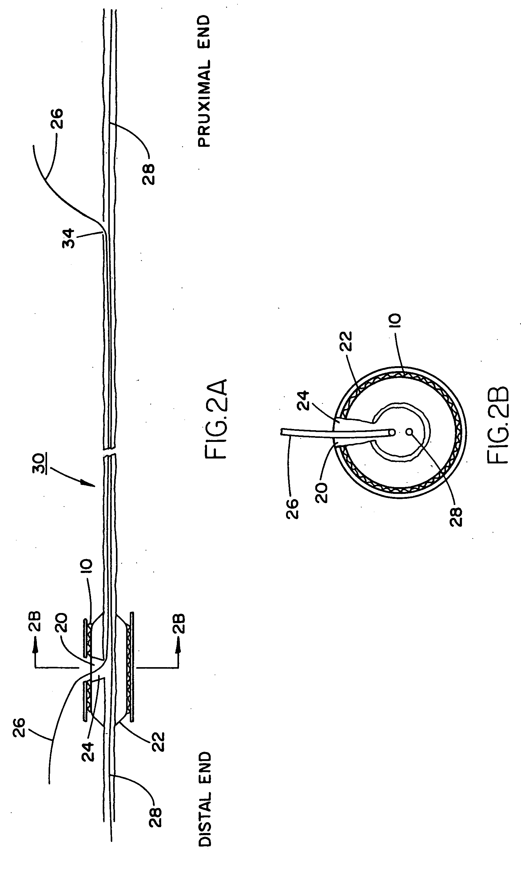
[0022] Accordingly, pursuant to the invention, there is provided a unique and sophisticated advantageous design for a stent and integrated balloon stent delivery system enabling the conveyance to and deployment of the stent at a particular site in the lumen or body vessel of a patient. In particular, such as is contemplated for the treatment of a bifurcated vessel or lesion, there is provided a structure which incorporates a specialized stent and a side hole or aperture in the center portion of a balloon or by means of an integrated slit-tube embedded on a balloon surface, and / or along the shaft of a balloon catheter, in the form of either a separate structure or as an integrated delivery system for dilatation and / or placement of the stent or plurality of stents, while concurrently maintaining the patency of and access to both branches of the bifurcated vessel branch points. Although, especially directed to the treatment of bifurcated vessels or lesions, the inventive structure is not limited thereto.

Problems solved by technology

Although numerous patents and publications are currently in existence, which are directed to the disclosures of diverse types of luminal stents and delivery systems, including devices such as balloons employed in angioplasty for inserting and locating the luminal stents at specified sites and thereafter fixed in the patient's vessel, for instance, as in a blood vessel or other locales, these are not specifically designed and generally not suited for the treatment of bifurcated vessels and lesions.
However, in this patent, there is no capability or concept of employing the stent and balloon delivery system for the treatment of bifurcated vessels and lesions in a manner analogous to that provided by the present invention.

Method used


Image

  • Stent and balloon system for bifurcated vessels and lesions
  • Stent and balloon system for bifurcated vessels and lesions
  • Stent and balloon system for bifurcated vessels and lesions

Examples


Embodiment Construction

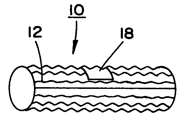
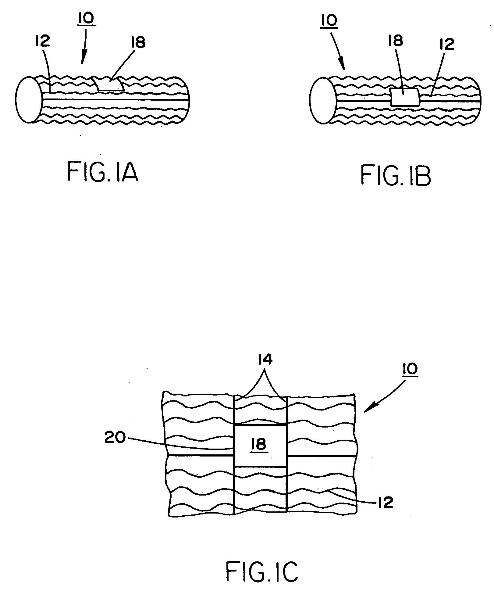
[0042] Referring in detail to the drawings, and particularly FIGS. 1A to 1C, there is illustrated a stent 10, which may include a wavylinear strut design 12 along the axial length thereof. The stent 10, which is radially expandable or contractable, includes a plurality of transverse strut connecting members 14, and may be constituted of either a medically or biocompatible plastic material or a surgical grade metal; for example, such as Nitinol (nickel-titanium alloy), as is well known in the stent implanting technology. Furthermore, the stent 10 may also be equipped, coated or impregnated with a drug or antibiotic dispensing system or release layer, as is known and presently employed in the medical art technology.

[0043] As illustrated in the drawings, a center region 18 of the stent 10 may possess a larger-sized open cell area 20, in effect, fewer of the struts 12, 14 in order to provide a larger opening 20, as shown in particular detail in FIG. 1C of the drawings, and as elucidate...


PUM


Abstract

A stent and a percutaneous balloon system for the placement of the stent in the lumen of a patient, and particularly relates to a stent and balloon system, which may be an integrated delivery system for dilatation and / or placement of a stent or stents especially for but not limited to bifurcated vessels and lesions. Moreover, disclosed is a method of deploying the stent at a particular site through the intermediary of the inventive balloon system.

Description

REFERENCE TO RELATED APPLICATION [0001] The present application claims the benefit of the filing date of Dec. 10, 2003 of U.S. Provisional Patent Application No. 60 / 528,315.BACKGROUND OF THE INVENTION [0002] 1. Field of the Invention [0003] The present invention relates to a stent and to a percutaneous balloon system facilitating the placement of the stent in the lumen of a patient. More particularly, the invention pertains to a stent and balloon system, which may constitute an integrated delivery system for dilatation and / or the placement of a stent or of stents, which is especially intended for, but not limited to applications in connection with bifurcated vessels and lesions. Moreover, the invention is also directed to the provision of a novel method of deploying the stent at a particular site through the intermediary of the inventive balloon system. [0004] In essence, the medical technology has at this time been extensively developed with regard to the concepts of developing the...

Claims


Application Information

Patent Timeline
Patent Type & Authority Applications(United States)
IPC IPC(8): A61F2/06A61F2/82
CPCA61F2/82A61F2/852A61F2250/006A61F2/958A61F2002/067A61F2/954
Inventor WONG, SHING-CHIU
Owner WONG SHING CHIU
Learn More