
Error estimate concerning a target device's location operable to move in a wireless environment

a wireless environment and target device technology, applied in the field of positioning technique, can solve problems such as grossly inaccurate location estimation

Active Publication Date: 2005-06-16
AIRISTA FLOW INC +1
View PDF8 Cites 113 Cited by
  • Summary
  • Abstract
  • Description
  • Claims
  • Application Information

AI Technical Summary

Benefits of technology

[0020] Another preferred embodiment of the invention comprises displaying a map showing several sample points and graphically indicating the error estimate at each sample point. Such a map provides a quick visual estimate of the reliability of positioning at various locations.
[0021] According to another preferred embodiment of the invention, there is shown, superimposed on a map, an area within which the target device is located with a predetermined probability n, wherein n is a value from, say, 80 to 100%. For instance, the continuous area may be an ellipse. For example, such an area allows a user to see whether there are any nearby danger spots that should be avoided.
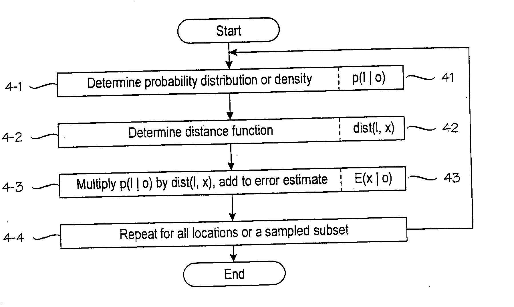
[0025] To implement the above method, based on equation 3, one needs to determine the probability distribution or density over the future observations. A preferable way to approximate this is as follows. When computing EE(x) from equation 3, the probability distribution or density p(o) is assumed to be the computed probability distribution or density based on past observations made at the sample point closest to the location x. The efficiency of the algorithm can be improved if E(x|o) is approximated by dist(l*,x), wherein l* is the point estimate produced by a positioning system after seeing observation o.

Problems solved by technology

It is possible for two or more remote locations to have near-identical sets of signal values, and a location estimate may be grossly inaccurate.

Method used


Image

  • Error estimate concerning a target device's location operable to move in a wireless environment
  • Error estimate concerning a target device's location operable to move in a wireless environment
  • Error estimate concerning a target device's location operable to move in a wireless environment

Examples


Embodiment Construction

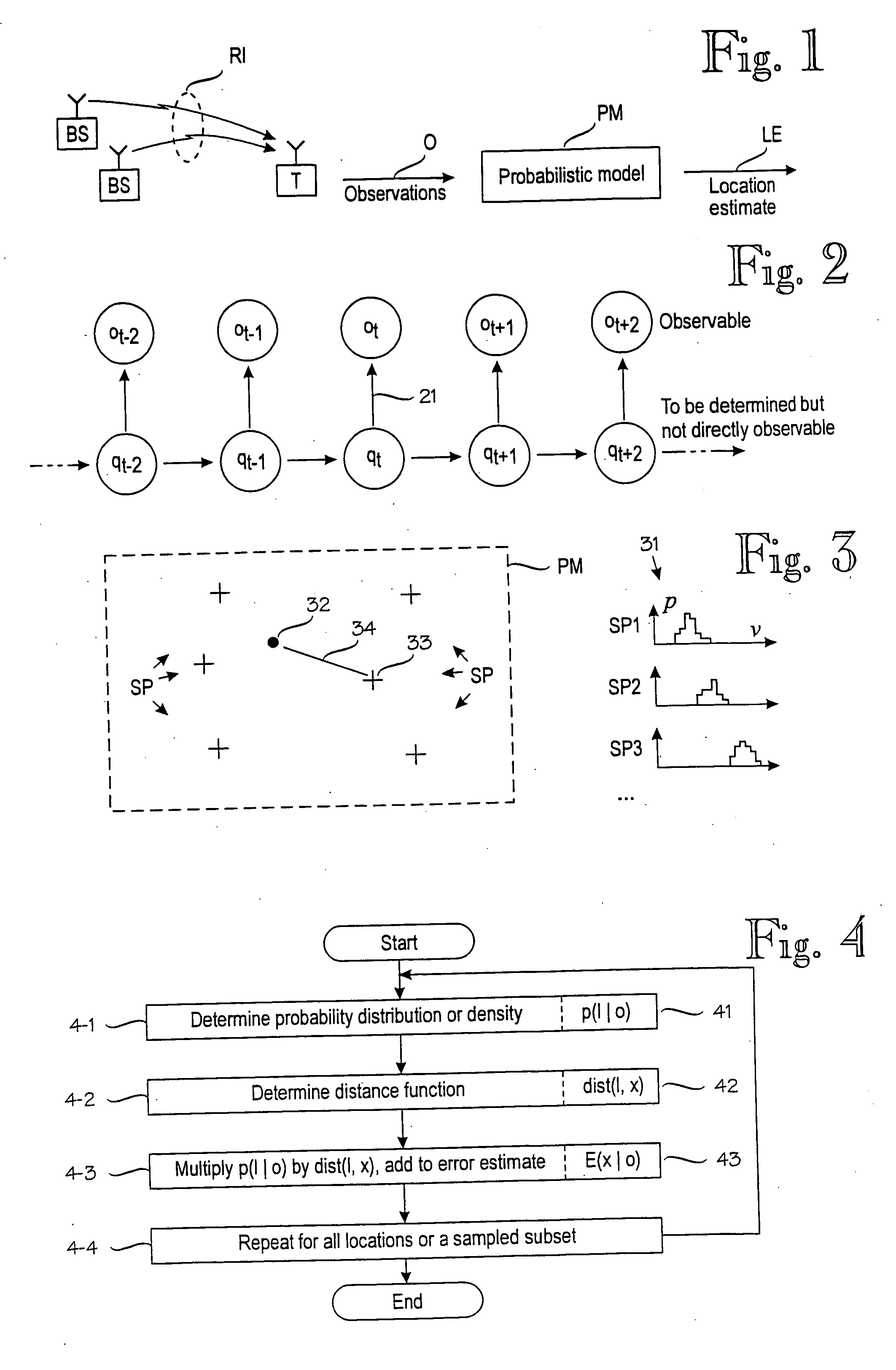
[0037] A reference is again made to FIG. 2 that shows a series of signal value observations ot−2 through ot+2. For each of the observations, there is a respective location qt−2 through qt+2 along the target device's path. This relationship is shown by arrow 21. The direction of the arrow 21 implies that the location qt determines the signal values comprised in the observation ot but the converse is not true. In other words, we can only directly observe the signal values and there is no simple relationship from the observations ot to the corresponding locations qt. On open sea, a signal value decreases predictably with the distance from the transmitter but in virtually all environments in which the invention will be used, a direct path from the transmitter is frequently blocked, and when it is not, it is not the only path taken by transmissions. Depending on phase, transmissions via multiple paths may combine constructively or destructively. Thus the relationship from location to sig...


PUM


Abstract

A method for determining an error estimate concerning a target device's location. The target device moves and communicates in a wireless environment using signals having at least one measurable signal value. A probabilistic model of the wireless environment indicates a probability distribution for signal values at several sample points in the wireless environment. A set of observations of signal values is made and the target device's location is estimated based on the probabilistic model and the set of observations. The error estimate (43) is determined as a combination of products over several sample points (SP). Each product comprises a probability distribution (41) for the sample point in question being the target device's location and a distance function (43) between the sample point in question and the target device's estimated location.

Description

[0001] This is a continuation of International Application No. PCT / FI03 / 0041 1, filed May 27, 2003, which claims priority from Finnish Application No. 20021045, filed May 31, 2002, the contents of both of which are incorporated herein by reference.BACKGROUND OF THE INVENTION [0002] The invention relates generally to a positioning technique in which a target device's location is estimated on the basis of one or more observations on the target device's wireless communication environment. FIG. 1 schematically illustrates an example of such a positioning technique. A target device T communicates with base stations BS via a radio interface RI. In this example, the communication is assumed to be radio communication. The target device T observes signal values at the radio interface RI. The observations O are applied to a probabilistic model PM that models the target device's wireless communication environment and produces a location estimate LE. As used herein, a target device is a device ...

Claims


Application Information

Patent Timeline
Patent Type & Authority Applications(United States)
IPC IPC(8): G01S5/02H04L12/28H04W64/00H04W84/12
CPCG01S5/02H04W84/12H04W64/00G01S5/0252G01S5/0244
Inventor MYLLYMAKI, PETRIKONTKANEN, PETRIROOS, TEEMUVALTONEN, KIMMOLAHTINEN, JUSSIWETTIG, HANNESTUOMINEN, ANTTITIRRI, HENRY
Owner AIRISTA FLOW INC
Learn More