Dust separation system

a technology of dust separation system and dust filter, which is applied in the direction of separation process, cleaning filter means, cleaning equipment, etc., can solve the problems of reducing the pressure drop (and thus the vacuuming power) at the surface being vacuumed, prolonging the filter life, and inconvenient replacement of such bags

Inactive Publication Date: 2005-06-23
ELECTROLUX HOME CARE PRODS
View PDF43 Cites 76 Cited by
  • Summary
  • Abstract
  • Description
  • Claims
  • Application Information

AI Technical Summary

Problems solved by technology

Although many previous vacuums have used a flexible bag as the dirt receptacle, the cost and inconvenience of replacing such bags has led to an increased preference for bagless vacuums.
Although bagless vacuums often provide suitable initial vacuuming performance, their filters tend to become clogged during use as debris accumulates on the filter surface, which results in a reduction in the pressure drop (and thus the vacuuming power) at the surface being vacuumed.
Although cleaning the filter between uses prolongs the filter life, over time, debris becomes permanently embedded in the filter, despite efforts to clean them.
Such clogging leads to reduced vacuuming power, and reduced user satisfaction.
In many cases, replacement filters can be relatively costly, or may no longer be available.
Furthermore, bagless vacuum filters can sometimes be rapidly clogged by large volumes of large particles tha...

Method used


Image

  • Dust separation system
  • Dust separation system
  • Dust separation system

Examples


Embodiment Construction

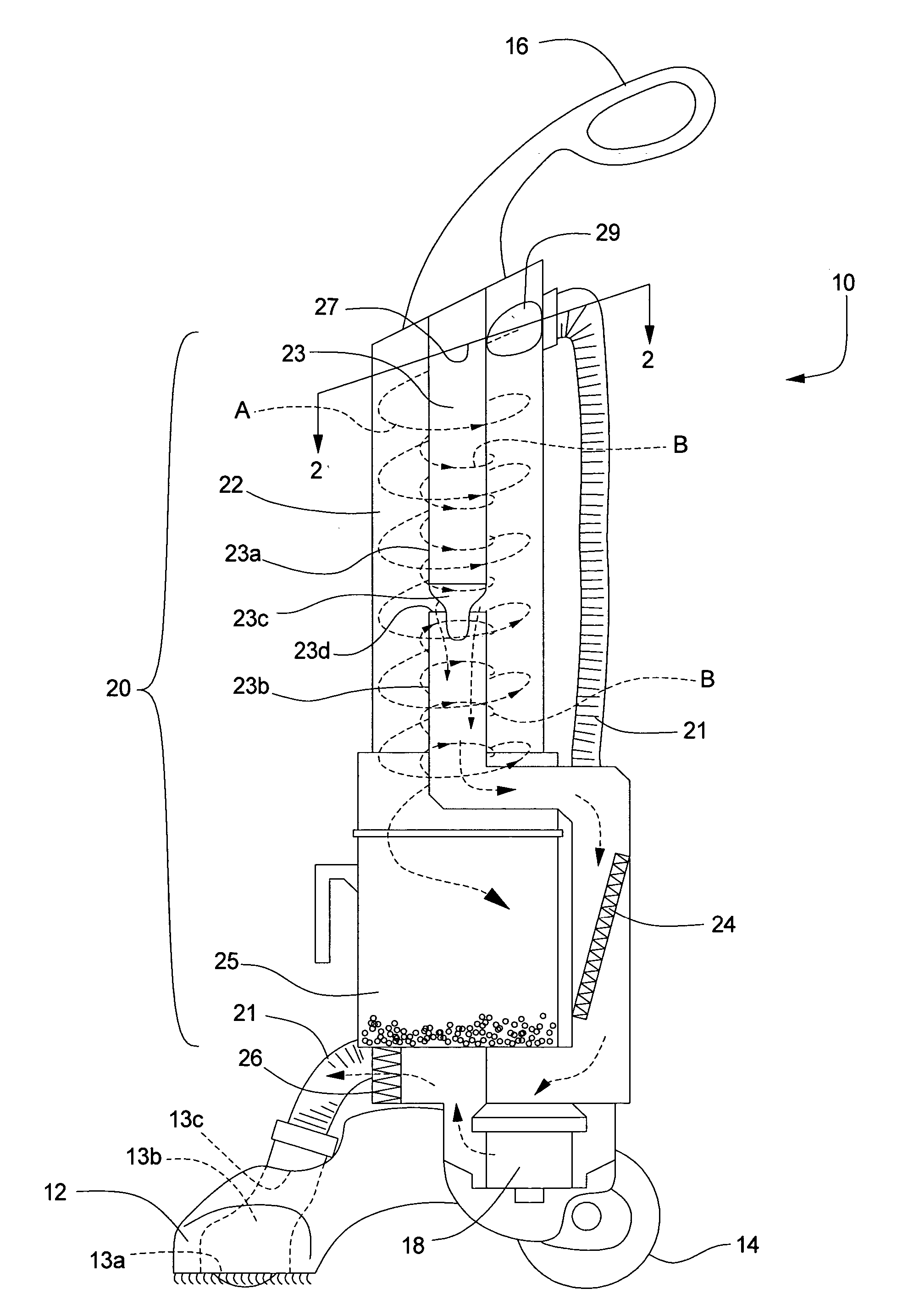
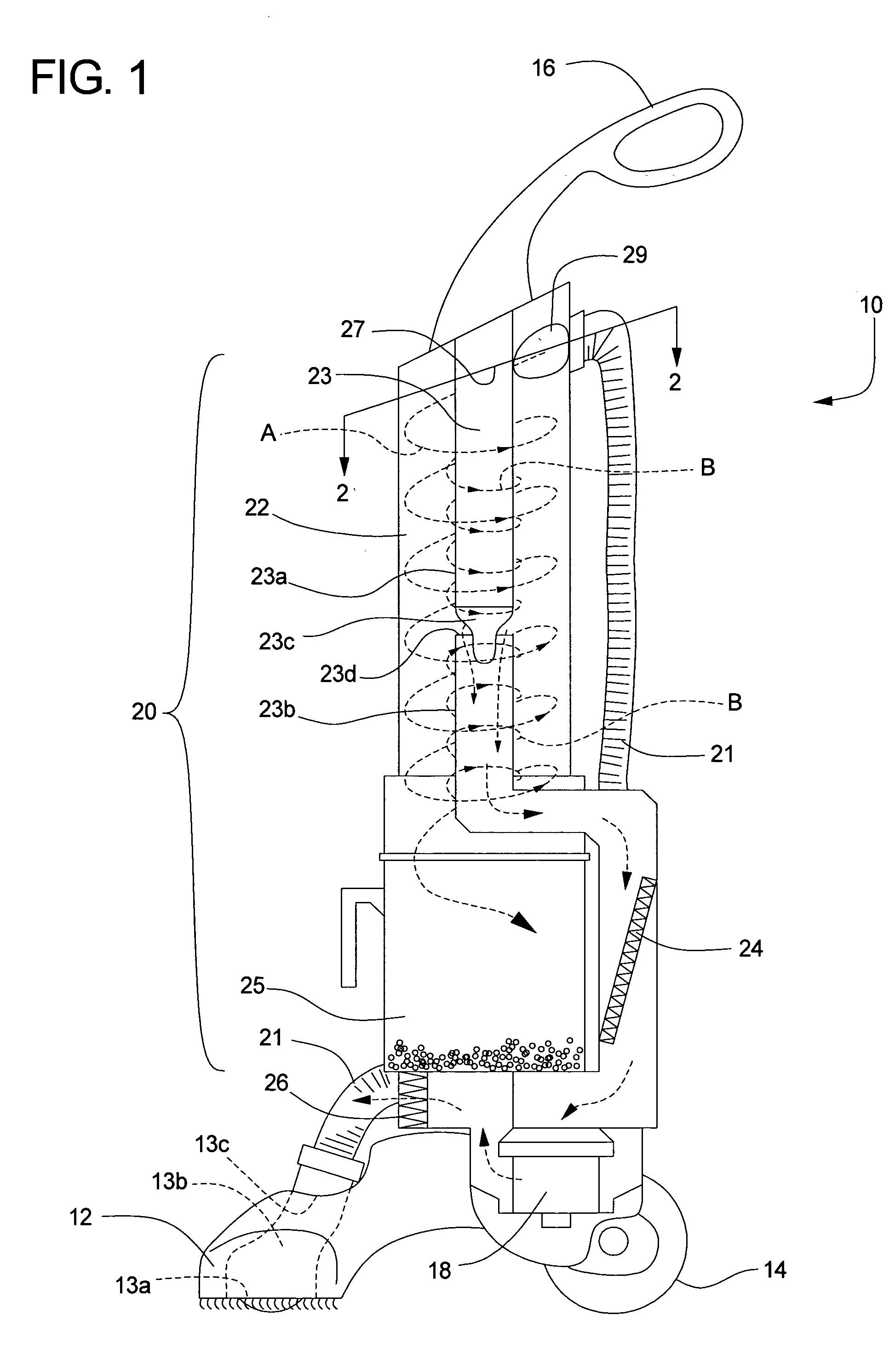
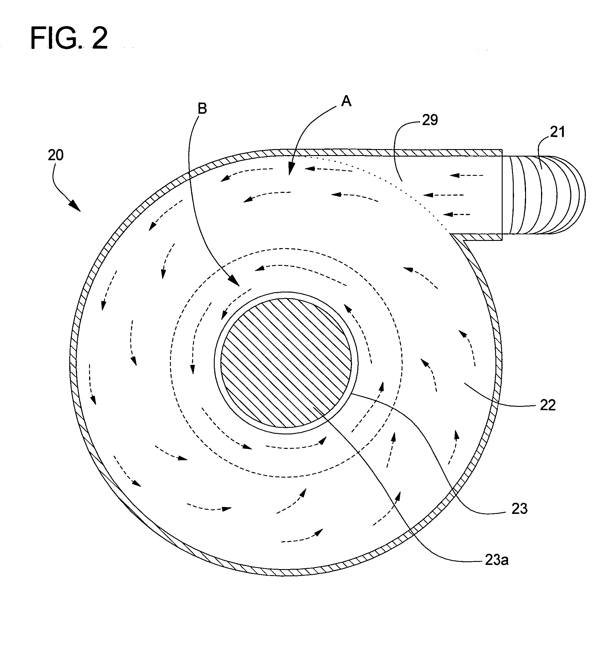
[0050] One of the objects of the invention is to provide a vacuum cleaner employing a device to create a spiraling column of airflow to facilitate the separation of particles, dust and other debris from the airflow in which they are entrained. To this end, one vacuum cleaner according the preferred embodiments includes a generally cylindrical separating chamber within which resides a central obstruction such as a plastic or PVC tube. A chamber entry port is positioned in the vicinity of one end of the obstruction and oriented to direct the incoming air and entrained debris into the chamber at an angle. A return air inlet is positioned in the obstruction itself, and is placed in fluid communication with a suction source to provide the vacuum necessary to operate the device. As such, the obstruction is formed by a closed tube and a hollow tube. A removable debris collection chamber is positioned below the separating chamber to collect dirt, dust and other debris. Baffles or other devi...


PUM

PropertyMeasurementUnit
Lengthaaaaaaaaaa
Flow rateaaaaaaaaaa
Diameteraaaaaaaaaa

Abstract

An upright vacuum cleaner having a nozzle adapted to be traversed on a surface to be cleaned, and having an internal passage defined by a nozzle inlet positioned to be substantially adjacent the surface to be cleaned and a nozzle outlet remote from the nozzle inlet. A handle is pivotally attached to the nozzle, and a suction motor is provided in the nozzle or the handle. The suction motor has a suction motor inlet, and is adapted to generate a working air flow through the nozzle and into the suction motor inlet. The vacuum includes a separation system having an outer wall, a closed tube having at least a portion of its length located within the outer wall and forming a separation chamber between the outer wall and the closed tube, a separation chamber inlet in fluid communication with the nozzle outlet and adapted to impart a tangential component to the working air flow as it flows through the separation chamber, and a hollow tube that is generally coaxially aligned with the closed tube and has a tube inlet at an end adjacent the closed tube and a tube outlet at an end opposite the closed tube. The tube outlet is in fluid communication with the suction motor inlet. The device also includes a collection chamber for receiving dirt separated from the working air flow.

Description

CROSS-REFERENCE TO RELATED APPLICATIONS [0001] This application claims priority to U.S. Provisional Application No. 60 / 524,910, filed Nov. 26, 2003, which is incorporated herein by reference in its entirety.FIELD OF THE INVENTION [0002] This invention relates to a dust separation system and particularly to dust separation systems for use in vacuum cleaners. BACKGROUND OF THE INVENTION [0003] In conventional vacuum cleaners (vacuums), dirt laden air is ducted into the vacuum and deposited into a receptacle supported on or within the vacuum housing. Although many previous vacuums have used a flexible bag as the dirt receptacle, the cost and inconvenience of replacing such bags has led to an increased preference for bagless vacuums. Bagless vacuums separate dirt by cyclonic action and / or duct the stream of dirt-laden air through a reusable filter that filters the dirt particles from the air stream before exhausting the filtered air stream back into the atmosphere. Various different typ...

Claims


Application Information

Patent Timeline
IPC IPC(8): A47LA47L5/28A47L5/36A47L9/10A47L9/16
CPCA47L5/28A47L5/362A47L9/1658A47L9/1616A47L9/1608
Inventor DAVIDSHOFER, DON
Owner ELECTROLUX HOME CARE PRODS
Why Eureka
Try Eureka