Separation system, components of a separation system and methods of making and using them

a separation system and separation system technology, applied in the field of separation systems and components, to achieve the effect of increasing the homogen increasing the uniformity of particle size, and increasing the size distribution and uniformity of separation effective openings throughout the polymer

Inactive Publication Date: 2006-07-11
DIONEX CORP
View PDF104 Cites 76 Cited by
  • Summary
  • Abstract
  • Description
  • Claims
  • Application Information

AI Technical Summary

Benefits of technology

[0090]In making size-compensated polymers for use in separation systems, the characteristics for a given type of separation can be tailored with a given polymer to the application, by altering the amount of pressure applied during polymerization or and in the case of some polymers such as used in forming reverse phase separation media applying pressure when used or when otherwise brought into contact with a polar solvent such as an aqueous solvent or washing fluid. After the nature of the polymer itself has been selected for a class of applications, columns can be made and tested. Based on the tests, the characteristics can be altered in some columns by applying pressure. It is believed that the application of pressure in some columns increases the uniformity of particle size and either because of the change in particle size of for other reasons, the size distribution and uniformity of separation effective openings throughout the polymer is increased. The increase in homogeniety of the particle size and pore size improves resolution. An increase in pressure generally improves capacity and resolution and the pressure-time gradient. It is believed that in some columns micropores are greatly reduced or eliminated thus reducing zone spreading by the application of pressure during polymerization and/or during use or washing of the polymer with polar solutions.
[0091]From the above description it can be understood that the novel monolithic solid support of this invention has several advantages, such as for example: (1) it provides chromatogr

Problems solved by technology

However, packing with non-porous particles has extremely low surface area which is detrimental to the purification process (as opposed to the analytical process) because the purification process requires high sample loading.
The use of very small packed particles requires either high pressure which is difficult in most of the separation process using current instrumentation or low velocity, which can increase the time for a given separation (sometimes expressed in H per minute).
The large size of the particles and their lack of homogeneity result in a lack of homogeneity in the pore size distribution.
The prior art plugs or solid supports formed of porous polymers have lower homogeneity of pore size, less desirable surface features and voids in their outer wall creating by wall effect and thus higher zone spreading and lower efficiency than desired in separation systems.
The prior art also fails to provide an adequate solution to a problem related to shrinkage that occurs during polymerization and shrinkage that occurs after polymerization in some prior art porous polymers.
The problem of shrinkage during polymerization occurs because monomers are randomly dispersed in the polymerization solution and the polymers consist of orderly structured monomers.
One of the problems with shrinkage after polymerization occurs because of the incompatibility of a highly hydrophilic polymer support with a highly hydrophilic aqueous mobile phase or other highly polar mobile phase such as for example, a solution having less than 5–8 percent organic solvent content.
Shrinkage of the porous polymeric materials used in separation systems and their components during polymerization results in irregular voids on the surface of the porous polymers and irregularity of the pore size inside the polymer, which are detrimental to the column efficiency and the reproducibility of the production process.
The columns with large channels in the prior art patents cited above have low surface area and capacity.
The low capacities of the columns are detrimental for purification process which requires high sample loadings.
In spite of much effort, time and expense in trying to solve the problems of shrinkage, the prior art fails to show a solution to reduced capacity.
Because of the above phenomena and/or other deficiencies, the columns prepared by the above methods have several disadvantages, such as for example: (1) they provide columns with little more or less resolution than commercially available columns packed with beads; (2) the separations obtained by these methods have little more or no better resolution and speed than the conventional columns packed with either silica beads or polymer beads, particularly with respect to separation of large molecules; (3) the wide pore size distribution that results from stacking of the irregular particles with various shapes and sizes lowers the column efficiency; (4) the non-homogeneity of the pore sizes resulting from the non-homogeneity of the particle sizes and shapes in the above materials contribute heavily to the zone spreading; (5) the large amount of micropores in the above materials also contributes greatly to the zone spreading; and (6) shrinkage of the material used in the columns reduces the efficiency of the columns.
These problems limit their use in high resolution chromatography.
This reduces the shrinkage but is detrimental to the capacity and retention capacity factor of the columns which require high amount of functional monomers.
There is nothing mentioned in these paten

Method used


Image

  • Separation system, components of a separation system and methods of making and using them
  • Separation system, components of a separation system and methods of making and using them
  • Separation system, components of a separation system and methods of making and using them

Examples


example 1

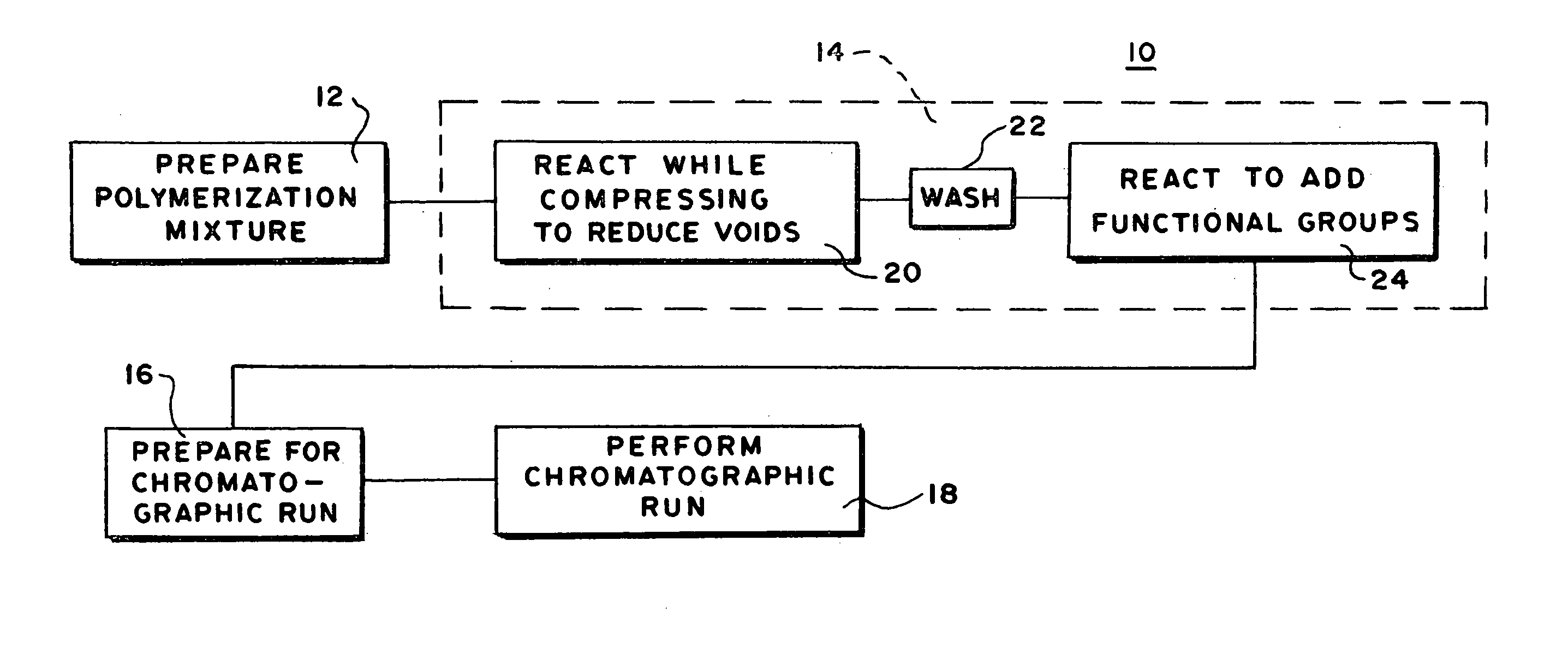
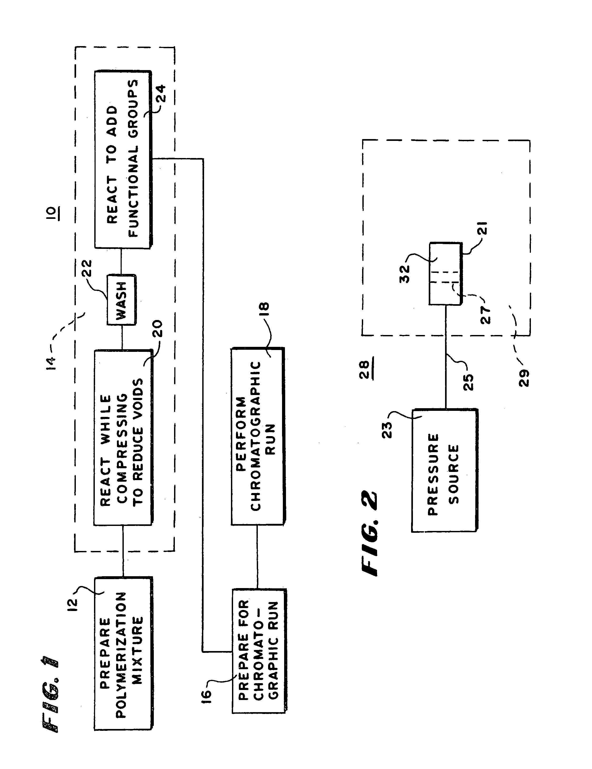
[0258]A polymerization solution was prepared as following: Weighed 1.2 g of glycidyl methacrylate (GMA), 0.80 g of ethylene dimethacrylate (EDMA) (polymerization mixture 1) and 0.02 g of 2,2=-azobisisobutyronitrile (AIBN) into a 20 ml sample vial and shook the mixture gently until it became a homogeneous solution; Weighed 2.55 g of cyclohexanol (CHOH) and 0.45 g of dodecanol (DODOH) into this solution and shook it until it is homogeneous. The polymerization mixture was degassed as in Degassing Procedure.

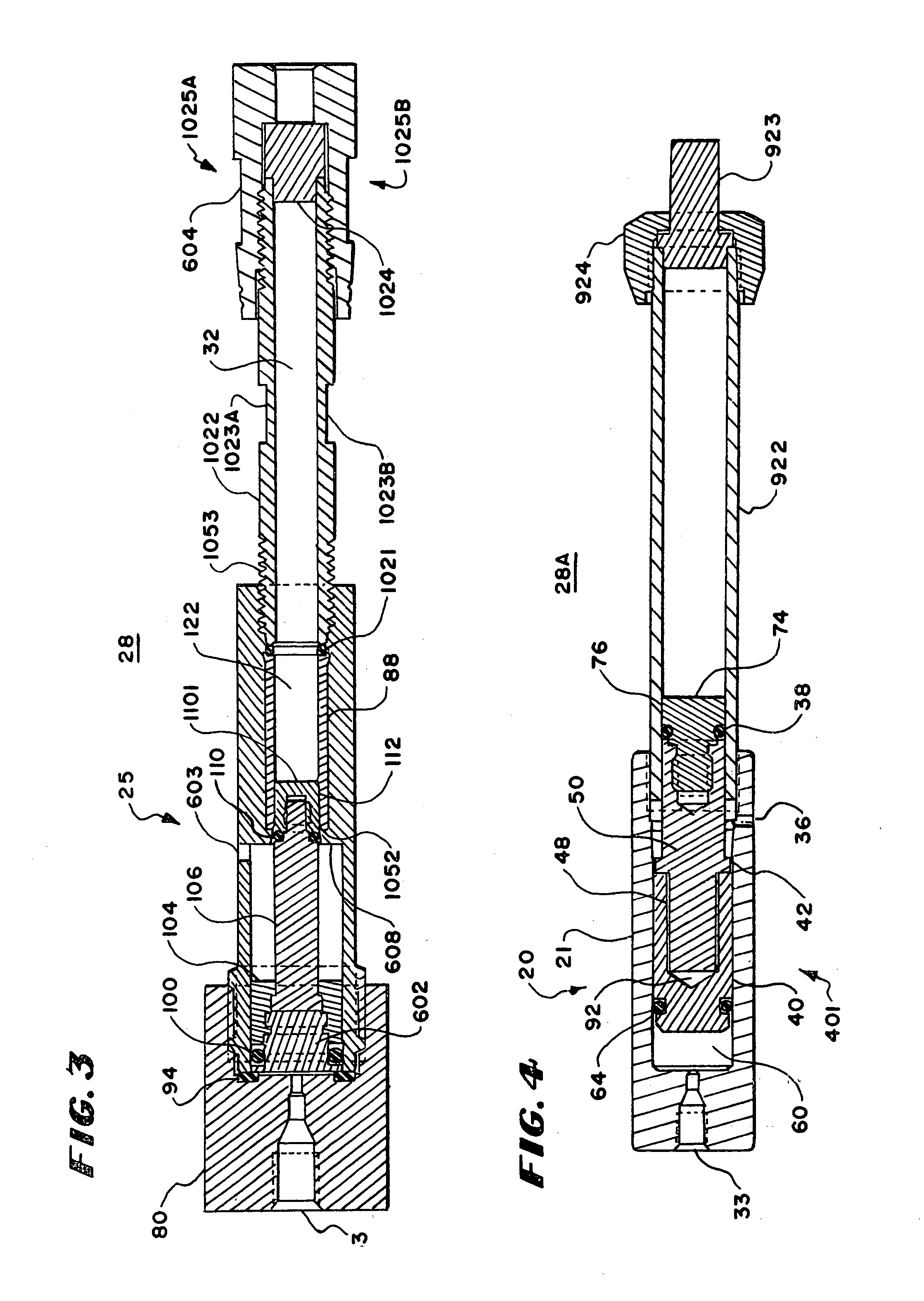
[0259]An empty stainless steel column (4.6 mm inner i.d. and 50 mm length), one end of which was sealed by a pressuring device shown in FIG. 4, was filled with this solution until the column is full. A PEEK-plug contained in the stainless steel screw cap, which was the original cap for the column shown in the same figure, was used to seal the other end of the column. The device of FIG. 3 was connected to a syringe pump. Water was used as the medium to generate the pressure of 120 psi...

example 2

[0271]A polymerization solution was prepared as Example 1 with the following polymerization solution: 2.0 g GMA, 2.5 g 2-(acryloyloxyethyl)trimethylammonium methyl sulfate (ATMS, 80%), 6.0 g EDMA, 7.5 g 1,4-butanediol, 6.75 g propanol, 0.75 g water and 0.1 g AIBN.

[0272]An empty glass column (10 mm inner i.d. and 100 mm length), one end of which was sealed by a pressuring device shown in FIG. 4, was filled with this solution until the column is full. A TEFLON-plug contained in the PEEK screw cap shown in the same figure, was used to seal the other end of the column. The device of FIG. 4 was connected to a syringe pump. No air was inside the column. This column was placed into a water bath upright at 60?C and kept for 15 minutes. Then the column was pressurized to 120 psi by syringe pump using water as the medium, and kept for 20 hours. After polymerization, the column was taken out of the water bath and cooled to room temperature.

[0273]The device of FIG. 4 was detached from the syrin...

example 3

[0282]Two columns were prepared as in Example 1 and 2 with the following solution: 17.5 g DVB, 19.8 g tetra(ethylene glycol), 10.2 g tetra(ethylene glycol) dimethyl ether, and 0.18 g AIBN. After wash with acetonitrile, the column was further washed with 20 bed volume of water at the flow rate of 16 ml / min. The manually positioned pistons in both ends were compressed into the column. This column was then washed with acetonitrile containing 0.15% trifluoroacetic acid and characterized by LC characterization method 1a and 1b. The resolutions of these columns for both protein and peptide separation were improved greatly over the columns made in the Comparative Examples. The capacities were more than 5 times higher. The back pressures of these columns were low. High resolutions were achieved with the mobile phase gradient starting from 100% water containing 0.15% TFA. No wall effect was found in these columns. The proteins and peptides pre-eluted out of the column in the columns from Com...


PUM

PropertyMeasurementUnit
Sizeaaaaaaaaaa
Radiusaaaaaaaaaa
Temperatureaaaaaaaaaa

Abstract

Permeable polymeric monolithic materials are prepared in a column casing. In one embodiment, the permeable polymeric monolithic materials are polymerized while pressure is applied through a piston having a smooth piston head in contact with the polymerization mixture. The pressure eliminates wall effect and changes the structure in the column. Similarly, some columns that have a tendency to swell in the presence of aqueous solutions and pressurized while the solution is applied to prevent swelling and wall effect. This procedure also changes the structure in the column. The size of the separation effective openings can be controlled by the amount of the pressure and pores eliminated. Uniformity in the direction flow is improved by controlling polymerization with radiation rather than with conducted heat.

Description

RELATED CASES[0001]This application is a continuation in part of U.S. patent application Ser. No. 10 / 180,350 filed Jun. 26, 2002, now U.S. Pat. No. 6,749,749 in the names of Shaofeng Xie and Robert W. Allington for SEPARATION SYSTEM, COMPONENTS OF A SEPARATION SYSTEM AND METHODS OF MAKING AND USING THEM.BACKGROUND OF THE INVENTION[0002]This invention relates to separation systems and their components and more particularly to separation systems and components involving monolithic permeable polymeric materials.[0003]Monolithic macroporous materials such as for example organic monolithic macroporous polymeric materials and monolithic silica packings are known as components for separation systems such as chromatographic or extraction systems. One class of such materials is formed as a monolithic macroporous polymer plug or solid support produced by polymerizing one or more monomers in a polymerization mixture that includes at least a porogen. It is known for some polymerization mixtures...

Claims


Application Information

Patent Timeline
IPC IPC(8): B01D15/08B01D15/20B01J20/281B01J8/00B01J19/00B01J19/18B01J20/283B01J20/285C08F2/00G01N30/16G01N30/46G01N30/52G01N30/56G01N30/80G01N30/88
CPCB01D15/206B01J20/3064B01J19/0013B01J19/18B01J20/283B01J20/285G01N30/56B01J8/0005B01J2219/00162B01J2220/54B01J2220/82G01N2030/528G01N2030/567G01N2030/522G01N30/30
Inventor ALLINGTON, ROBERT W.XIE, SHAOFENGJIANG, TAOXU, MINGCHENG
Owner DIONEX CORP
Why Eureka
Try Eureka