Due to limitations on the reaction process and technical conditions in the early stage, further scale-up was not suitable even though the development of F-T three-phase reactor had been proved in the lab scale.
Major issues were: 1) test result was no better than the conventional
fixed bed reactor; 2) the three-phase suspension bed reactor requires larger reactor volume; 3) reactor needs to be resistant to acids; 4) large recycle volume and
high energy consumption are needed in order to get
complete mixing; and 5) difficulty in removing products from the reactor.
During the late 1980s up to 1990s, some research results in fact demonstrated the minimum dimension of the
pilot test facility that meets the requirements of
industrial reactor scale-up; which also led developers to realize that too low reactor height and
tower inlet gas velocity is lack of
engineering significance.
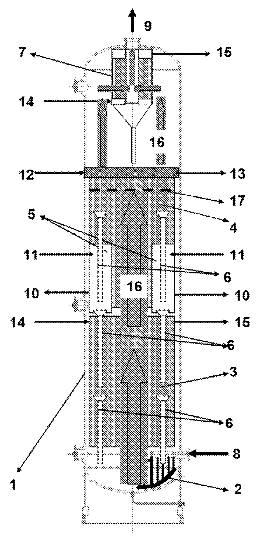
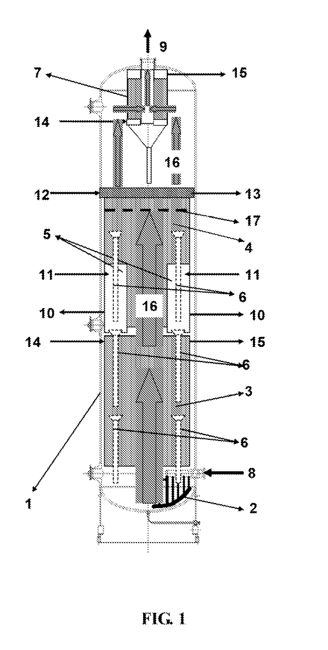
1. The gas distribution issue: the research and development on the gas distributor of the gas-liquid-
solid three-phase (slurry) F-T synthesis reactor is closely connected to the whole reactor development, with academic attention focused on how to make gas distribution uniform and to generate bubbles as small as possible, while the basic fact is that the gas distributor of large scale reactors under highly turbulent conditions is only effective within a limited space above the distributor and the whole bed is re-mixed and distributed by turbulence and internal members has been neglected. Within a practical reactor, the role of gas distributor, besides uniformly distributing the reactor inlet gas over the cross-section at the bottom of the reactor, is, to a large extent, to prevent
settling of catalyst by agitation via injecting gas from the gas distributor at the bottom of the reactor, and to prevent blockage by accidental entry of slurry into the gas distributor. These issues were not considered in public materials. For example, U.S. Pat. No. 5,905,094 refers to a kind of gas distributor, which uses a design of a series axially enlarged apertures on the
clapboard on the upper part of the
clapboard located in the reactor bottom. Major issues with the design are the difficulty in fabricating apertures (openings) on the gas distributor for feed
gas passing through while providing no definite methods in strengthening the
clapboard strength. Meanwhile, if the reactor inlet gas is accidentally stopped and leads to catalyst particles blockage at the above mentioned openings, the system will encounter problems during restart-up, with part of openings blocked and therefore causing non-uniform gas distribution. Thus application of this technology requires a series ancillary means to guarantee no harmful result happens to the reactor operation under all circumstances. Nevertheless, no public materials were found regarding these relevant ancillary process means; CN 1233454C refers to a kind of overall structure found in an
engineering design handbook (e.g., Perry's Chemical Engineer's Handbook, Sixth Edition, McGrew-Hill, 1984) where relative simple gas distributor designs can be found, and the gas introduction and distribution can be realized by setting up clapboards, with gas ejected into the three-
phase reaction zone via the downwards pointed small nozzles (above the upper surface of the clapboard) connected to the primary distribution conduit. Problems with this design are complexity in fabricating nozzles, the still high risk of
nozzle blockage, and no relevant public materials on measures for preventing blockage.
2. Efficient design of heat exchange system: the F-T synthesis process is a typical energy
type conversion process. From energy conversion point of view, synthesis gas is converted to hydrocarbons while 15-25% energy input to the reactor is converted to reaction heat. Thus efficient heat exchange is required to guarantee: 1) efficient
temperature control of the reactor bed; 2) efficient reaction heat removal; and 3) heat input during startup. The basic process requirement on the configuration of the
heat exchanger within a large-scale suspension bed reactor is to benefit fluid dynamics within the reactor and the capability for efficient heat removal. So far there appears to be no systematic feasible design for the heat exchange parts in such an F-T synthesis suspension bed reactor, e.g., the U.S. Pat. No. 6,201,031 B1 indicated the use of multiple structure of U-tube connected in series, and the patent CN1233451C referred to pipes in a spiral or detoured
multiple pass heat exchange
pipe. Also mentioned in some patents is the difficulty in the
layout of these shell-and-tube structures inside reactor, the improper
layout of heat exchanger structure can cause a series of problems.
First is non-uniform disturbance on flow field; second is excess blockage within local volume which is harmful to slurry recycle; third, the heat exchange area layout is limited and thus influences the reaction heat
recovery efficiency. Other issues include structure vibration,
stress concentration, etc., all of which have no systematic solution.
3. Efficient separation of liquid
wax product and catalyst: the heavy products from F-T synthesis is in liquid form under
reaction conditions and will gradually accumulate inside the three-phase suspension bed reactor, which have to be on-lined removed from the reactor. Because this heavy liquid
wax generally coexists with F-T synthesis catalyst in the slurry form, the primary means of realizing this operation is continuous liquid-solid separation. Because the catalyst particle size used for F-T synthesis is generally in the range of 30-200 micron (more than 90%), it is suitable to use
filtration as liquid-solid separation means. Liquid-solid filtration separation is a conventional
engineering problem. All kind of filtration technologies as standard
unit operation can be found in standard
chemical engineering handbook and publications (e.g.,
Chemical Engineering, Vol. 2, Fourth Edition, Butterworth-Heinemann, Linacre House, Jordan Hill, Oxford OX2 8DP, 1991, Handbook of Separation Techniques for Chemical Engineers, Second Edition, McGrew-Hill, 1988). Among them, catalyst
separation technology suitable for the three-phase suspension bed (slurry bed reactor) uses filtration pipes (
candle design or shell-and-tube design). Compared to conventional filters, the space in the reactor is naturally taken as the higher pressure container for pressurized filtration, with the porous filtration
pipe surface as support for filtered cake. The filtered cake reenters the three-phase bed to continue its
catalytic function via washing by the turbulent three-phase fluid and back flow cleaning measures. In publicized U.S. Pat. No. 6,462,098B1, filtration process principle was tested for specific F-T synthesis catalyst and
reactor system. The filtration device used was similar to
candle structure with outlet conduit installed at the bottom part for transporting separated heavy wax from the reactor, at the same time
backflow cleaning operation can also be carried out. For example,
Chinese patent CN1233453C reported a set of automatic filtration equipment, wherein shell-and-
tube structure equipped with outlet
pipe devices, with upper part for back blowing and lower part for conducting away filtrate. This filtration equipment can be set up to five
layers. In these technical materials, no structural optimization design during reactor integration has been mentioned in order to meet the following synthesis
process requirements: 1) the effect of filtration structure on fluid dynamics and furthermore effect on filtration environment, 2) disturbance on flow field by filtration devices and outlet conduit extended from the device, which may possibly make the filtering media of the filtration device exposed to the sustained large bubbles and how to prevent the thus generated inefficient filtration problem, 3) structural configuration of filtration modules and how to realize uniform distribution of fluid dynamics for each of the filtering element within filter group, and 4) how to seamlessly integrate reactor internal filter separation apparatus and heat exchange apparatus and to prevent the catalyst from being exposed to excess temperature, which could accelerate the deactivation of the whole reaction catalyst bed, especially in
filter cake where heat removal capacity in the filtration area is relatively weak.
4. Liquid-solid strengthened mixing in three-phase reactor: For F-T synthesis reactor, because there is no complete design scheme for internal members such as heat exchangers, filtration separation device inside the whole reactor space, the efficiency for fluid dynamics strengthening means in published materials is different. Axially along the reactor, internal members are mounted by sections, the proper allocation of which can strengthen fluid dynamic characteristics, e.g., the size distribution of bubbles may be more beneficial to the efficient operation of synthesis reaction, and also fluid dynamics distribution characteristics radially along the reactor cross section may be improved. However, the existence of these internal members leads to many complex structural factors for flow field axially along the reactor. The flow field of the main body part inside a section of the internal members shows uniformity, while at the both ends there may show a trend of flow field structure degradation, which can cause local recycle inside the three-
phase reaction zone and influence the catalyst
distribution uniformity across the whole bed and the efficiency of heat exchange and separation components. In U.S. Pat. Nos. 5,382,748, RE37229E, U.S. Pat. No. 6,201,031B1, it was reported that vertical
drop tube could improve the slurry recycle axially across the reactor and thus was beneficial to the catalyst
distribution uniformity axially across the reactor. This also proves the
correctness of the general principles of the three-phase fluidized reactor. These materials did not consider the relation between reaction overall structure and
drop tube configuration and structures, thus did not meet the basic requirements of optimization design.
5. The problem of reactor outlet mist entrainment and high solid contents in condensates: In previous study, there was no reasonable scheme for the reactor top design, which may cause too much liquid and catalyst entrainment in the
reaction system and gas flow, and thus too high solid contents in the condensed heavy products. This negatively influences the efficiency of product workup technology and the secondary product purification, especially when accidentally there is too much foam or liquid overflow, for which there is no systematic solution to entrainment problems in
design plan. U.S. Pat. No. 6,265,452B1 presented a scheme to solve solid entrainment and extract part of the condensates by setting up pieces of members similar to
distillation trays inside
gas phase in the upper reactor space. This adds to the reactor structure complexity and it was not proved whether these trays / plates can operate normally under the solid entrainment conditions, especially in the case of malfunctioned overflow weir due to entrained solids, accidentally liquid overflow (when system suddenly experiences a pressure drop more than 0.1 Mpa). The aftermath would be serious.

