Pointing device for detecting hand-movement

a pointing device and hand-moving technology, applied in the field of pointing devices, can solve the problems of inability to change the content, user cannot move around the audience, and the cost of pointing devices is high

Inactive Publication Date: 2005-06-23
KYE SYST CORP
View PDF3 Cites 110 Cited by
  • Summary
  • Abstract
  • Description
  • Claims
  • Application Information

AI Technical Summary

Benefits of technology

[0009] It is an object of the present invention to provide a stable and precisely controlled pointing device, which can truly respond to hand-movements so as to move a cursor on a display of a computer system.

Problems solved by technology

However, it is not able to change the content, which must be programmed using a computer.
Thus, the user cannot move around the audience to provide a vivid presentation.
However, the pointing device is costly to produce because of the need for a very precise gyroscope to detect hand-movement of a user.
To train a user to precisely operate a trackball in the air (suspending the user's arm away from the working surface) is a very tough task.
However, the accelerometer fails to truly respond the complicated hand-movement in the air due to the impractical design.
According to an experiment conducted by the inventor, the pointing device disclosed in the patent is almost inoperative.

Method used


Image

  • Pointing device for detecting hand-movement
  • Pointing device for detecting hand-movement
  • Pointing device for detecting hand-movement

Examples


first embodiment

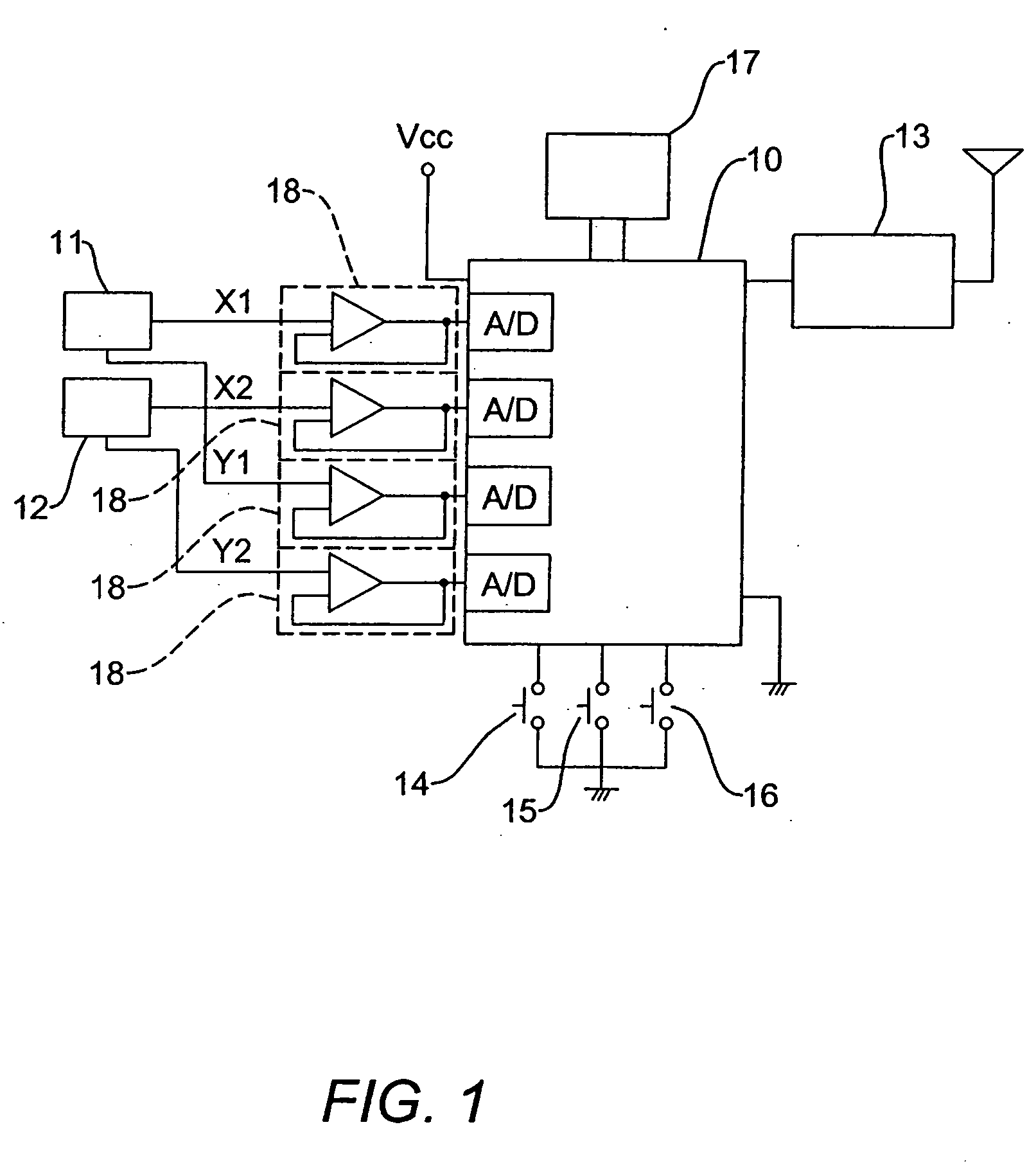
[0021] Referring to FIGS. 1, 3 and 5, the present invention comprises a micro control unit (MCU) 10; at least two accelerometers 11, 12 respectively located at a first position and a second position; and a wireless transmitting module 13 arranged to wirelessly transmit a cursor-moving signal sent from the MCU 10. When a user operates the pointing device 20, for example by waving it in the air, the MCU 10 calculates the difference in accelerations sensed by the two accelerometers 11, 12, and sends the cursor-moving signal to a computer system or the like. Therefore a cursor 32 on the display (not shown) of the computer system 30 will move correspondingly.

[0022] In order to stabilize the output voltages of accelerometers 11 and 12, voltage follower 18 is respectively located between sensors 11, 12 and the MCU 10. A plurality of function keys 14, 15, 16 and 17, representing different key codes, are coupled to the MCU 10. Therefore, when a user operates the pointing device 20 to move th...

second embodiment

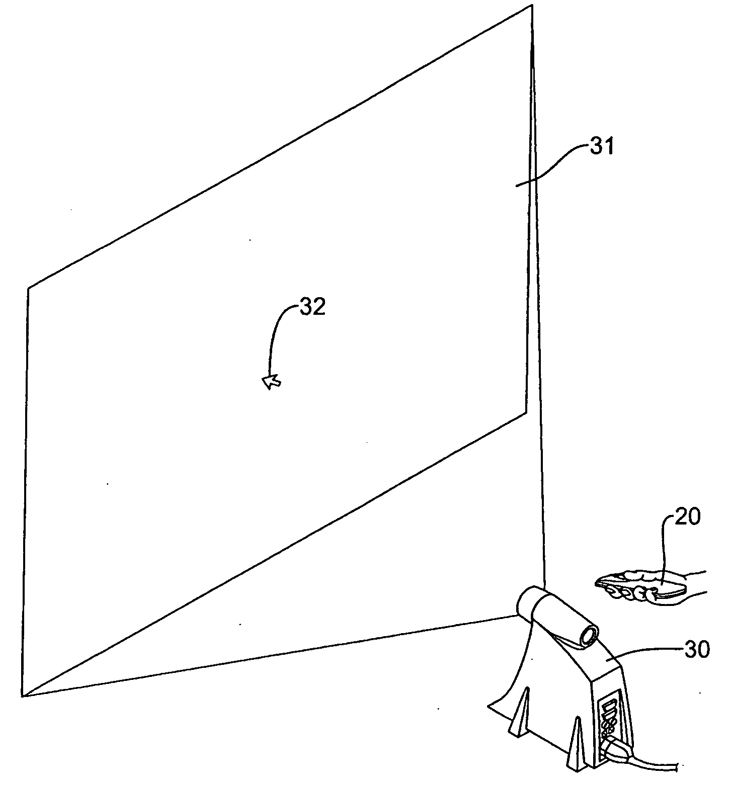
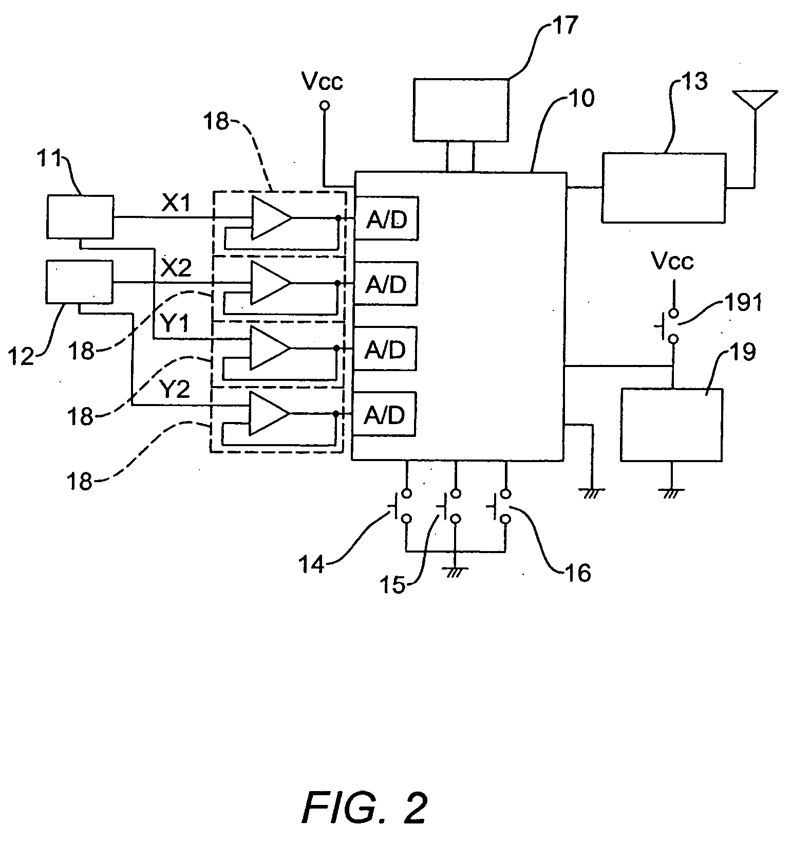
[0023] Referring to FIGS. 2 and 3, is the present invention. A laser pointer 19 is further incorporated within the pointing device 20. The laser pointer 19 connects to power supply Vcc via a switch 191, and MCU 10. When the switch 191 is activated, the laser pointer 19 is connected to the Vcc and emits a light beam. When a user operates the pointing device 20, a cursor 32 projected by a projector 30 on the screen 31 will move correspondingly. The user can move the beam over a screen 31 for highlighting a projected content. However the MCU 10 may also enter a sleep mode to stop working and save the power of the pointing device 20.

[0024] Referring to FIGS. 3 and 4, the shape or outline of the pointing device 20 can be ergonomically designed to match the hand, with the sensor 11 positioned at a front of the device and the sensor 12 positioned at a rear of the device. When the user operates the pointing device 20 in the air, the MCU 10 will receive two acceleration signals simultaneousl...


PUM


Abstract

The present invention discloses a pointing device for communicating with a computer system. The pointing device includes a micro control unit and at least two acceleration sensors respectively located at a first position and a second position. The pointing device may further include a wireless transmitting module that can wirelessly transmit a cursor-moving signal sent from the MCU. When a user operates the pointing device, the MCU calculates the difference in accelerations sensed by the two acceleration sensors, and sends the cursor-moving signal to the computer system. The pointing device further provides a laser pointer for facilitating the indication of content on a projected screen.

Description

BACKGROUND OF THE INVENTION [0001] 1. Field of the Invention [0002] The present invention relates to a pointing device for communicating with a computer system or the like, and in particular to a pointing device for controlling cursor movement on a display according to the outputs of two inertia or acceleration sensors, hereinafter “accelerometers,” for sensing changes in direction and speed of the pointing device. [0003] 2. Description of the Prior Art [0004] A conventional pointing device simply projects a laser light over a screen to highlight content relevant to a speech. However, it is not able to change the content, which must be programmed using a computer. [0005] On the other hand, a computer system is usually operated while a user sits at a table so as to utilize a pointing device moving on the table. Thus, the user cannot move around the audience to provide a vivid presentation. [0006] A small pointing device has been developed to overcome the inconvenience mentioned above...

Claims


Application Information

Patent Timeline
Patent Type & Authority Applications(United States)
IPC IPC(8): G06F3/033G09G5/00
CPCG06F3/0346
Inventor LIAO, ZHI-JIAN
Owner KYE SYST CORP
Why Eureka
Try Eureka