Wirelessly driven display system

a display system and wireless technology, applied in the field of display systems, can solve the problems of inconvenient and unmanageable wiring, poor aesthetic appearance, and limited distance between the display device and the signal generation devi

Inactive Publication Date: 2005-06-23
INNOLUX CORP
View PDF8 Cites 62 Cited by
  • Summary
  • Abstract
  • Description
  • Claims
  • Application Information

AI Technical Summary

Benefits of technology

[0007] One objective of the present invention is to provide a display system such that a control unit is integrated into an interface unit at a side of a first antenna, so as to shrink the display module size of a display device.
[0009] To achieve the above and other objectives, the present invention, in accordance with one particular embodiment, discloses a display system comprising a signal generation unit, an interface unit comprising a control unit and a transmitting unit, a first antenna, a second antenna, and a display device comprising a receiving unit, a display panel, an x-direction driver and a y-direction driver. The control unit of this particular embodiment is integrated in the interface unit so as to shrink the display module size of the display device.
[0010] In accordance with another particular embodiment of the present invention, a display system is disclosed comprising a signal processing device, an interface unit comprising a control unit and a first transceiver unit, a first antenna, a second antenna, and a touch-screen display device comprising a second transceiver unit, a touch-screen display panel, an x-direction driver and a y-direction driver. The control unit of this particular embodiment is also integrated in the interface unit so as to shrink the display module size of the display device, while the touch-screen display device is capable of two-way communication between the display device and the signal processing device.

Problems solved by technology

However, cable connections between a display device and a signal generation device limit the distance between the display device and the signal generation device to the length of the cable used.
Further, as more and more peripheral devices are connected to the signal generation device, a large amount of cables needs to be employed, resulting in inconvenient and unmanageable wiring and poor aesthetic appearance.

Method used


Image

  • Wirelessly driven display system
  • Wirelessly driven display system
  • Wirelessly driven display system

Examples


Embodiment Construction

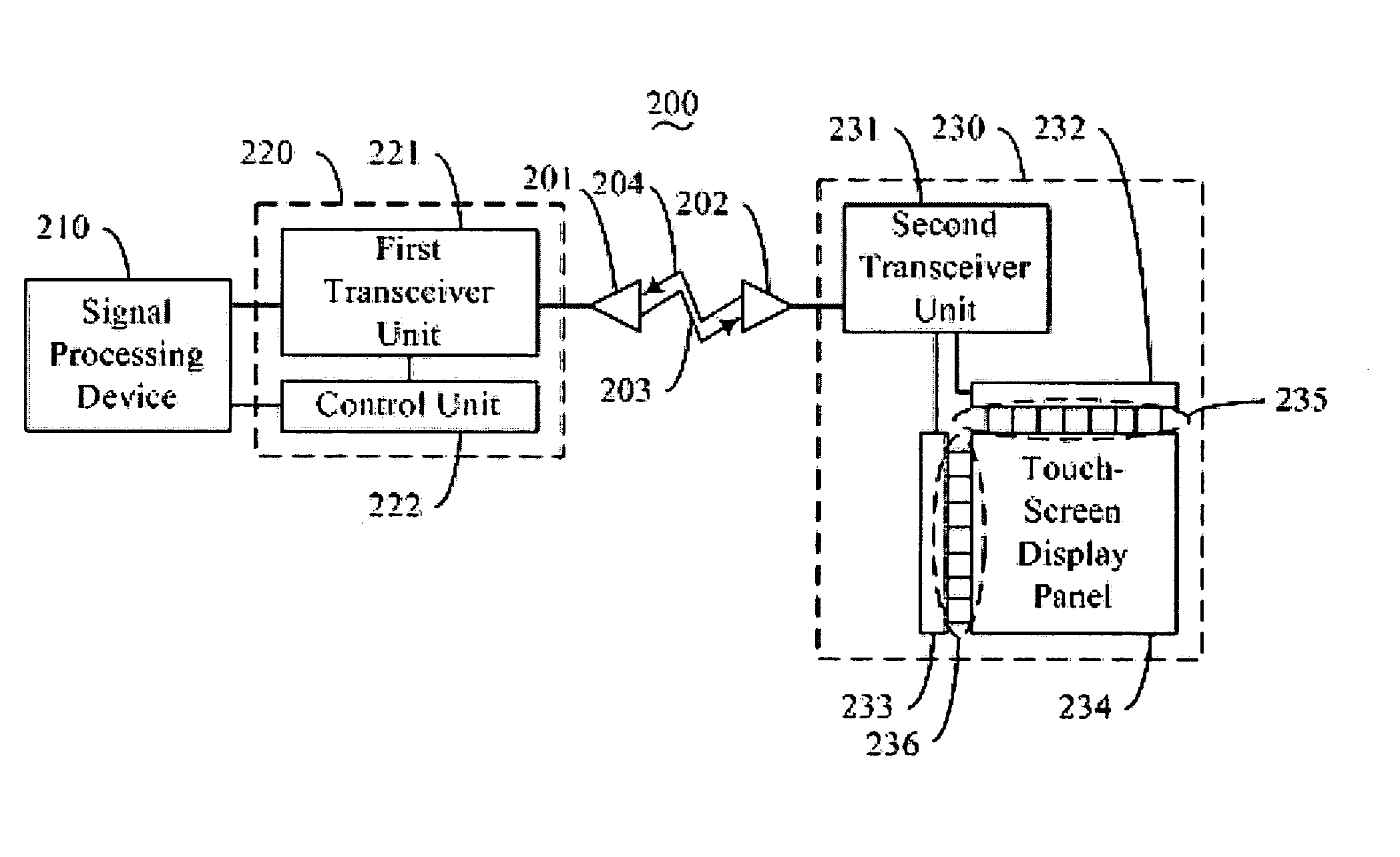
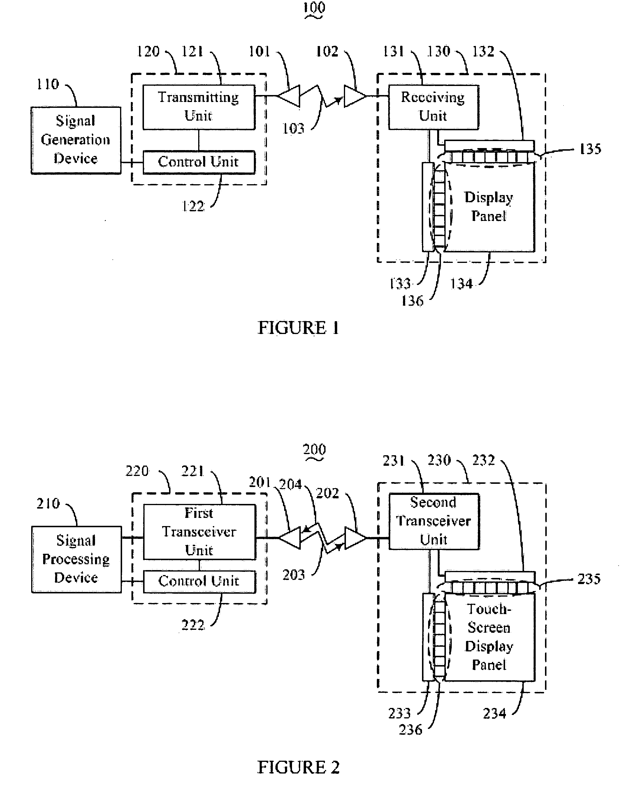
[0015] Referring to FIG. 1 a display system 100 in accordance with one particular embodiment of the present invention is illustrated. The display system 100 comprises a signal generation device 110, an interface unit 120 comprising a transmitting unit 121 and a control unit 122, a first antenna 101, a second antenna 102, and a display device 130 comprising a receiving unit 131, a x-direction driver 132, a y-direction driver 133 and a display panel 134. In this particular embodiment, the signal generation unit 110 is a personal computer, while in other particular embodiments, the signal generation unit 110 may alternatively be a server computer, a personal digital assistant, a television set, a television phone or a television conference system. The display device 130 in this particular embodiment is a thin film transistor liquid crystal display (TFT-LCD) device. The display device 130 may alternatively be a cathode ray tube (CRT) display device. The first antenna 101 and the second ...


PUM


Abstract

The present invention provides a display system (200) for wirelessly driving display devices. In one embodiment, the display system includes a signal processing unit (210), an interface unit (220) having a control unit (222), a first antenna (201), a second antenna (202) and a display device (230). In contrast to a conventional wirelessly driven display system, the control unit of the present invention is integrated into the interface unit. By doing so, the display area of the display device may be enlarged. Furthermore, the display system may also allow two-way communication between the display device and the signal processing unit by incorporating an input signal detector.

Description

BACKGROUND OF THE INVENTION [0001] 1. Field of the Invention [0002] The present invention relates generally to a display system, and more particularly, to a display system that is operated by means of wireless connections. [0003] 2. Prior Art [0004] Conventionally, a display device, such as a liquid crystal display, is connected to a signal generation device, such as a personal computer, through cables. However, cable connections between a display device and a signal generation device limit the distance between the display device and the signal generation device to the length of the cable used. Further, as more and more peripheral devices are connected to the signal generation device, a large amount of cables needs to be employed, resulting in inconvenient and unmanageable wiring and poor aesthetic appearance. Thus, wireless connections between signal generation devices and peripheral devices are gradually replacing cable connections. [0005] U.S. Pat. No. 6,492,973 issued to Kuroki ...

Claims


Application Information

Patent Timeline
Patent Type & Authority Applications(United States)
IPC IPC(8): G09G5/00
CPCG09G5/006
Inventor HSIEH, TSAU-HUAPANG, JIA-PANG
Owner INNOLUX CORP
Why Eureka
Try Eureka