Serial-to-ethernet conversion port

a serial to ethernet and port technology, applied in the direction of coupling device details, electrical discharge lamps, coupling device connections, etc., can solve the problems of not providing a modular rj 45 jack with a complete serial to ethernet conversion, known systems require a substantial footprint and occupy critical limited space, etc., to achieve the effect of simple and cost-effective, few connections

Inactive Publication Date: 2005-06-23
LANTRONIX
View PDF9 Cites 22 Cited by
  • Summary
  • Abstract
  • Description
  • Claims
  • Application Information

AI Technical Summary

Benefits of technology

[0010] The device of the present invention allows for adding Ethernet connectivity to a new product in a simple and cost-effective manner. The device of the present invention contains all required hardware and firmware for effective serial-to-Ethernet conversion and requires very few connections between a product's printed circuit board (typically 10 or less) and requires no more space than a typical RJ-45 jack.

Problems solved by technology

Because of the standard arrangement of the RJ-45 jack and attendant electronic circuitry components, known systems require a substantial footprint which takes up critical limited space.
In known devices, manufacturers have failed to place all of the components necessary for a complete conversion from serial to Ethernet within the standard jack housing.
In this regard, manufacturers have failed to provide a modular RJ 45 jack with complete serial to Ethernet conversion.

Method used


Image

  • Serial-to-ethernet conversion port
  • Serial-to-ethernet conversion port
  • Serial-to-ethernet conversion port

Examples


Embodiment Construction

[0026] The detailed description as set forth below in connection with the appended drawings is intended as a description of the presently preferred embodiments of the present invention, and does not represent the only embodiment of the present invention. It is understood that various modifications to the invention may be comprised by different embodiments and are also encompassed within the spirit and scope of the present invention.

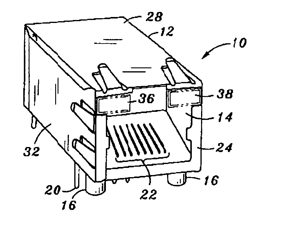
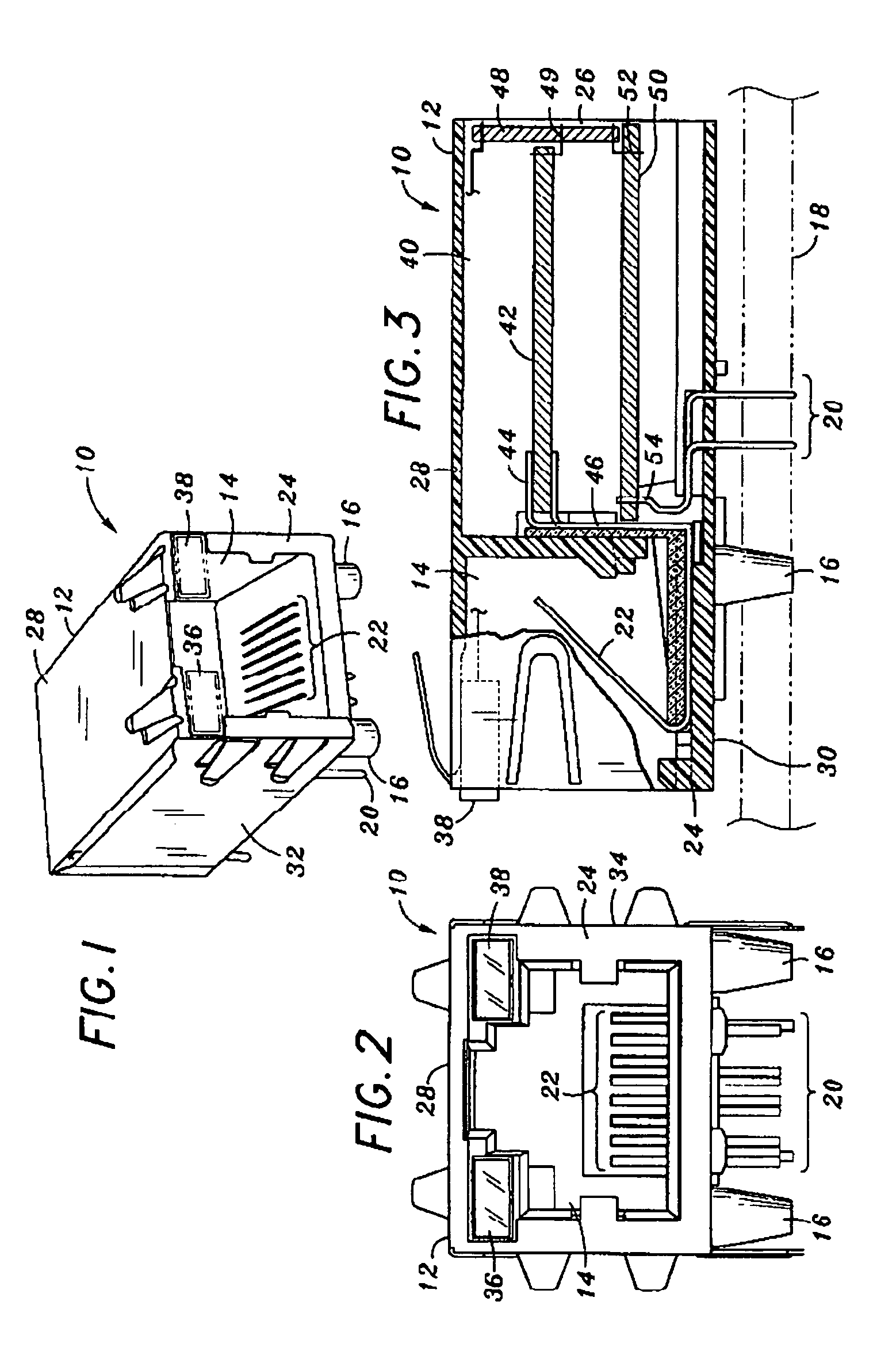
[0027] Referring particularly to FIGS. 1, 2 and 3, FIG. 1 shows a perspective front view of the Ethernet connector 10 of the present invention. FIG. 2 shows a front view of the connector 10 of the present invention. FIG. 3 shows a cut-away side view of the connector 10. Connector 10 comprises a generally rectangular housing 12. The front of the housing includes an open cavity 14. A metal Faraday shield covers the top, sides and back of the housing and provides for electromagnetic-radiation (EMR) protection. The connector 10 additionally includes spring b...


PUM


Abstract

The present invention relates to a serial-to-Ethernet modular converter jack and a method of fabricating of the same. The serial-to-Ethernet converter electronic components, including the control software stored in on-board memory, are miniaturized and housed entirely in an RJ-45 jack. The present invention is constructed of a shielded housing that defines an open front portion for a connector port. The housing of the present invention also includes a segregated interior chamber, which encases all of the electrical components necessary to complete a serial-to-Ethernet conversion of data. Lead pins electrically connected to the circuitry within the interior chamber, protrude from the based of the connector jack providing for a means to mate the jack to a circuit board. First, second and third circuit boards collectively incorporate the serial-to-Ethernet circuitry components. Both the first circuit board incorporating magnetic circuitry and the second circuit board incorporating control circuitry are positioned in generally horizontal parallel relation within the interior chamber. The second circuit board which defines opposed sides includes electronic components disposed upon the upper and lower of both sides of the second circuit board. The third circuit board, incorporating connections to the LEDs, is positioned generally perpendicular in relation to the first and second circuit boards and is structurally connected to the first and second circuit boards, additionally providing an electrical connection between the first and second boards. Alternative embodiments of the invention are disclosed and include various arrangement of the serial-to-Ethernet circuitry within the interior chamber of the housing.

Description

CROSS-REFERENCE TO RELATED APPLICATIONS [0001] This application is a continuation application of U.S. application Ser. No. 10 / 122,867 filed Apr. 15, 2002.BACKGROUND OF THE INVENTION [0002] The present invention relates to generally to Ethernet ports and the serial-to-Ethernet conversion associated with such ports. More particularly, the invention relates to the structure and method of fabrication of a serial-to-Ethernet converter housed completely within an Ethernet jack to provide profile reduction, and reduce manufacturing cost and complexity. Furthermore, the serial-to-Ethernet converter also contains general purpose programmable input / output pins (PIO). These PIOs can be used to control devices that have no microcontroller, and also read data from such devices. This integral RJ-45 / converter device can thus be used as a complete modular Ethernet interface for electronic devices that lack intelligence (no microcontroller). [0003] A Registered Jack-45 (RJ-45) is a wire connector us...

Claims


Application Information

Patent Timeline
Patent Type & Authority Applications(United States)
IPC IPC(8): H01R24/00H01R13/66H01R31/06H01R33/945H05K1/14
CPCH01R13/6658H01R13/6691H01R24/64H01R2201/04H05K1/144H01R31/06
Inventor BROWN, CURTIS D.BROWER, CHARLES J.
Owner LANTRONIX
Why Eureka
Try Eureka