
Transceiver for a base station with smart antenna and a switched beamforming method in downlink

a technology of switching beams and antennas, applied in diversity/multi-antenna systems, instruments, spatial transmit diversity, etc., can solve the problems of inability to apply adaptive beam weight vectors in uplink and reliability, inability to solve capacity problems and reliability problems at the same time, and achieve the effect of improving performance in downlink, facilitating the formation of downlink beams, and increasing the complexity of terminals or bases

Inactive Publication Date: 2005-06-23
ELECTRONICS & TELECOMM RES INST
View PDF10 Cites 76 Cited by
  • Summary
  • Abstract
  • Description
  • Claims
  • Application Information

AI Technical Summary

Benefits of technology

[0030] The advantage of the present invention is to provide a transceiver for a base station with a smart antenna and a beamforming method in downlink capable of easily forming a downlink beam by using an inner product of an uplink adaptive beam weight vector and a switched beam weight vector.
[0031] Another advantage of the present invention is to provide a transceiver for a base station with a smart antenna and a beamforming method in downlink capable of improving performance in downlink without increasing complexity of a terminal or a base station.
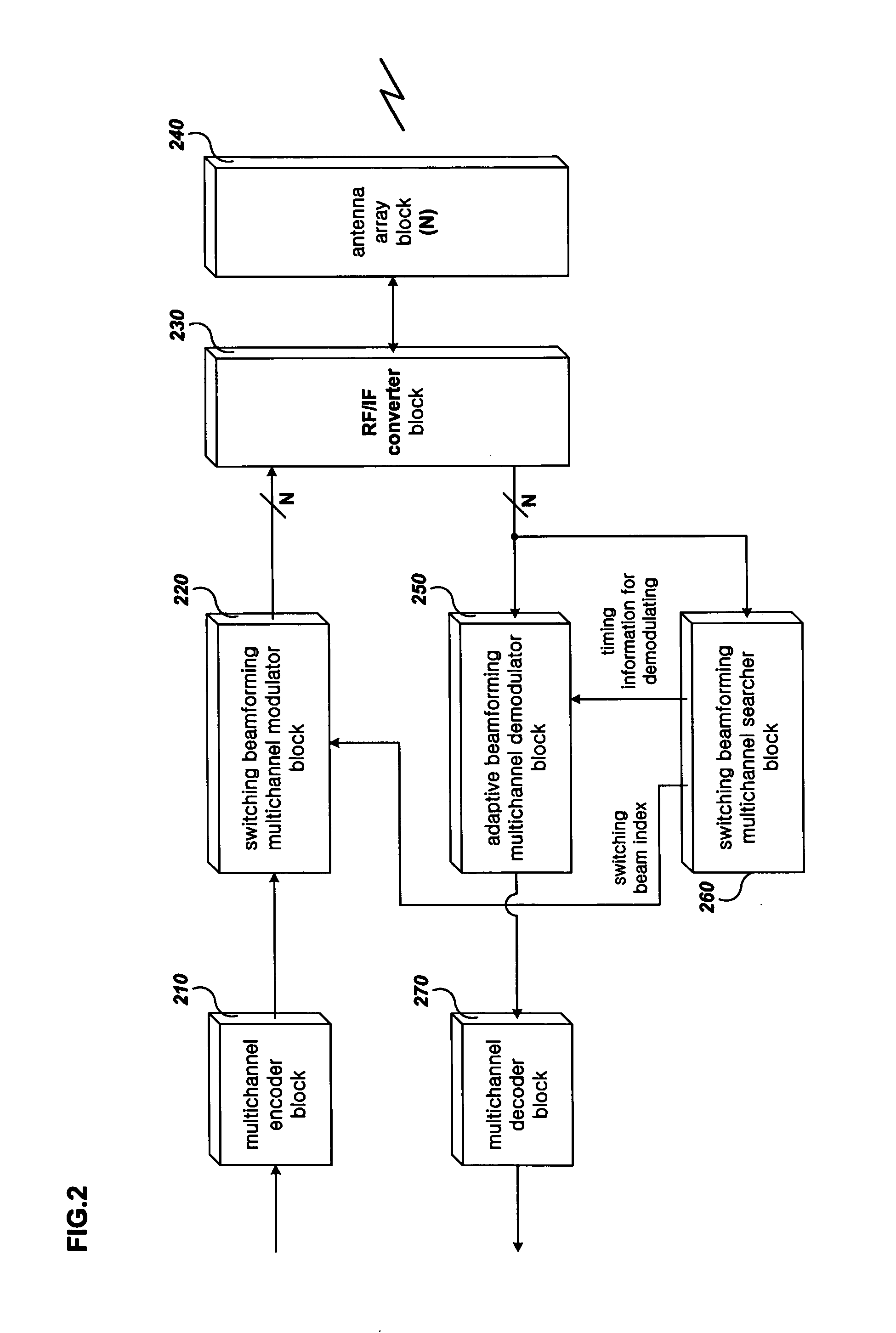
[0032] To achieve the advantage, the present invention provides a transceiver for a base station with a smart antenna, comprising: a multipath searching unit for searching multipath delay information for each demodulation channel for signals received through the plurality of antennas; a demodulating unit for forming an adaptive beam for each demodulation channel by using the multipath delay information for each demodulation channel for receiving signals and performing demodulation to the received signals and outputting at least one adaptive beam weight vector for each demodulation channel, the adaptive beam weight vector occurred during demodulation; a controlling unit for selecting at least one downlink beam index for each channel by using correlation of the adaptive beam weight vector and the pre-established plurality of switched beam weight vectors; and a modulating unit for selecting the downlink switched beams corresponding to at least one downlink beam index respectively and forming switching beam for modulating signals of each channel and outputting the modulated signals in downlink.
[0033] Here, the demodulating unit comprises a plurality of demodulators, and each demodulator may comprise: a plurality of adaptive beamforming finger blocks; and a combiner for combining the outputs from the plurality of adaptive beamforming finger blocks and outputting the combined outputs to a channel decoder.
[0034] Here, the adaptive beamforming finger blocks may comprise: an adaptive beam weight vector operator for real-time extracting the adaptive beam weight vector from the received signals by using the multipath delay information; a multiplier for real-time multiplying the received signals by the outputs from adaptive beam weight vector operator; and a finger for receiving the output from the multiplier and performing dispreading of the DS-CDMA signals by using the multipath delay information, and performing time-tracking, channel estimating, and coherent demodulation, and transferring the demodulated symbol to the combiner and continuously outputting a time averaged energy of the demodulated symbol.
[0035] Here, the adaptive beam finger block real-time provides the adaptive beam weight vector outputted from the adaptive weight vector operator and the symbol energy from the finger to the controlling unit.

Problems solved by technology

However, there are no known methods satisfying both reduction of the bandwidth and increase of reliability at the same time.
Thus, the known methods can not solve both a capacity problem and a reliability problem arising with the next generation mobile communication system.
The new method may restrict interference and noises by controlling beam pattern.
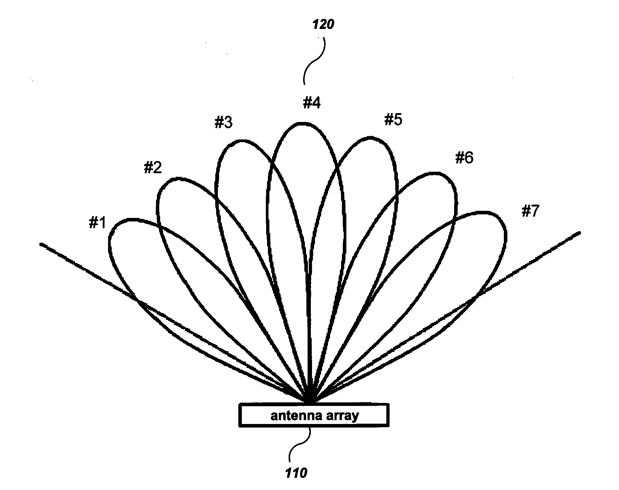
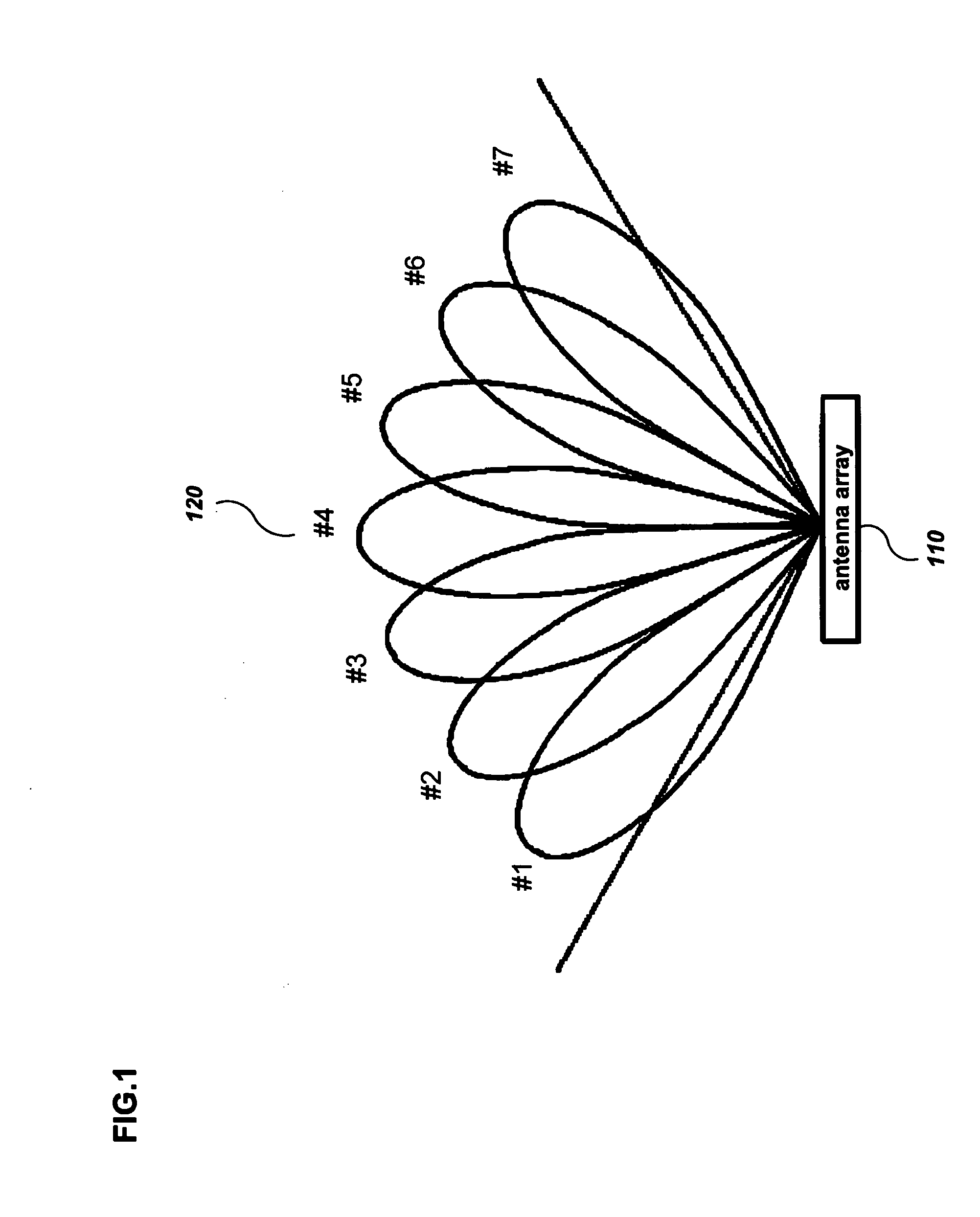
On the other hand, the switched beamforming method has a predetermined number of beams and predetermines the switched beam weight vector.
However, since frequencies in downlink and uplink are different in the frequency division multiplexing (FDD) method, the adaptive beam weight vector in uplink can not be applied in downlink.
However, errors can occur at the channel during feedback of the channel information or the performance can fall by feedback delay etc., when the characteristics of the channel are bad or the speed of the mobile station is high.
Further, since the mobile station continuously measures the characteristics of the channel in downlink and feedbacks the characteristics of the channel to the base station, the mobile station may become complicated.
However, since the invention uses the adaptive beamforming method using the feedback information from the mobile station in downlink, the performance can fall, when the characteristics of the channel are bad.
However, although this method can solve the problem of the pen loop beamforming method to some degree by using the downlink adaptive beamforming method, the complexity of the terminal or the base station can be increased.

Method used


Image

  • Transceiver for a base station with smart antenna and a switched beamforming method in downlink
  • Transceiver for a base station with smart antenna and a switched beamforming method in downlink
  • Transceiver for a base station with smart antenna and a switched beamforming method in downlink

Examples


Embodiment Construction

[0054] In the following detailed description, only the preferred embodiment of the invention has been shown and described, simply by way of illustration of the best mode contemplated by the inventor(s) of carrying out the invention. As will be realized, the invention is capable of modification in various obvious respects, all without departing from the invention. Accordingly, the drawings and description are to be regarded as illustrative in nature, and not restrictive. To clarify the present invention, parts which are not described in the specification are omitted, and parts for which similar descriptions are provided have the same reference numerals.

[0055] Hereinafter, a transceiver for a base station with a smart antenna and a switched beamforming method in downlink are described with reference to the appended drawings.

[0056]FIG. 3 shows a construction of a transceiver for a base station with multichannel for demodulating signals by forming an adaptive beam and using an adaptiv...


PUM


Abstract

Disclosed is a transceiver for a base station with a smart antenna having a plurality of antennas. The transceiver comprises: a multipath searching unit for searching multipath delay information for each demodulation channel; a demodulating unit for forming an adaptive beam for each demodulation channel by using the multipath delay information for each demodulation channel for receiving signals and performing demodulation to the received signals and outputting at least one adaptive beam weight vector; a controlling unit for selecting at least one downlink beam index for each channel; and a modulating unit for selecting the downlink switched beams and forming switching beam for modulating signals of each channel and outputting the modulated signals in downlink.

Description

CROSS REFERENCE TO RELATED APPLICATION [0001] This application claims priority to and the benefit of Korea Patent Application No. 2003-94126 filed on Dec. 19, 2003 and Application No. 2004-26722 filed on Apr. 19, 2004 in the Korean Intellectual Property Office, the entire content of which is incorporated herein by reference. BACKGROUND OF THE INVENTION [0002] (a) Field of the Invention [0003] The present invention relates to a transceiver for a base station with a smart antenna and a beamforming method in downlink. [0004] More specifically, the present invention relates to a transceiver for a base station with a smart antenna for transferring signals from the base station to a mobile station, and a beamforming method in downlink in a wireless communication system using an antenna array or the smart antenna. [0005] (b) Description of the Related Art [0006] A mobile communication system makes it possible to communicate any kind of data with certain parties anywhere and at any time at ...

Claims


Application Information

Patent Timeline
Patent Type & Authority Applications(United States)
IPC IPC(8): G01S19/05G01S19/11G01S19/21G01S19/29G01S19/46H01Q1/24H01Q3/24H01Q3/26H04B1/38H04B7/06H04B7/08
CPCH01Q1/246H01Q3/24H04B7/086H04B7/0617H01Q3/2605
Inventor KIM, IL-GYUJWA, HYE-KYUNGBANG, SEUNG-CHAN
Owner ELECTRONICS & TELECOMM RES INST
Learn More