Hybrid eye tracking system and associated methods

a technology of eye tracking and eye tracking, applied in the field of eye tracking systems and methods, can solve problems such as the difficulty of determining the visual axis from which to calculate the movement of treatment lasers

Inactive Publication Date: 2005-06-23
ALCON REFRACTIVEHORIZONS
View PDF10 Cites 26 Cited by
  • Summary
  • Abstract
  • Description
  • Claims
  • Application Information

AI Technical Summary

Benefits of technology

[0007] It is another object to provide a system and method for tracking eye moveme

Problems solved by technology

This movement makes it difficult to determine a visual axi

Method used


Image

  • Hybrid eye tracking system and associated methods
  • Hybrid eye tracking system and associated methods
  • Hybrid eye tracking system and associated methods

Examples


Embodiment Construction

[0018] A description of the preferred embodiments of the present invention will now be presented with reference to FIGS. 1-3.

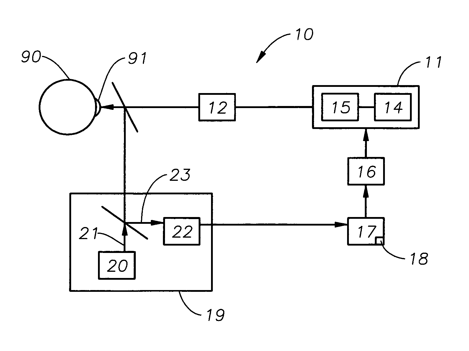
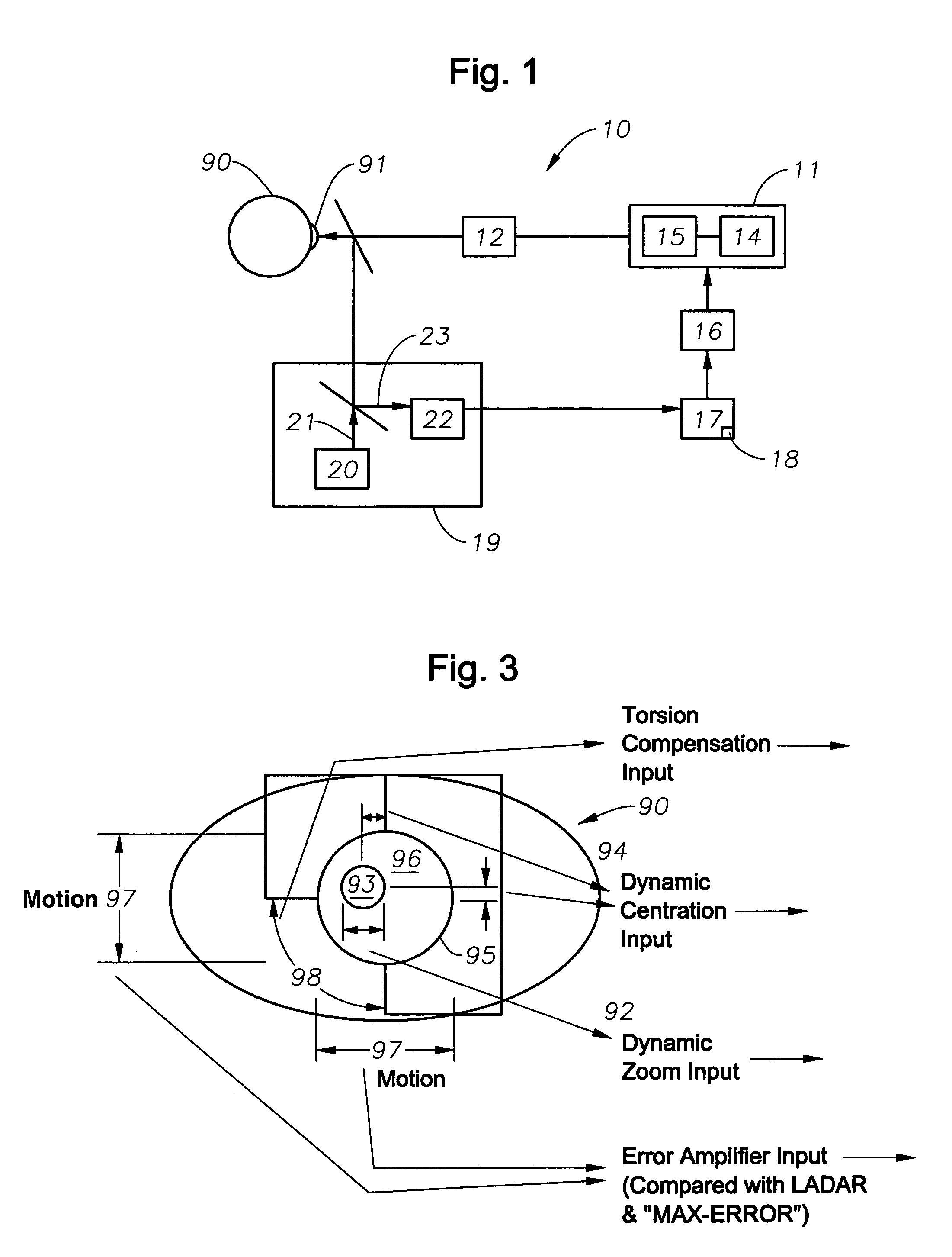
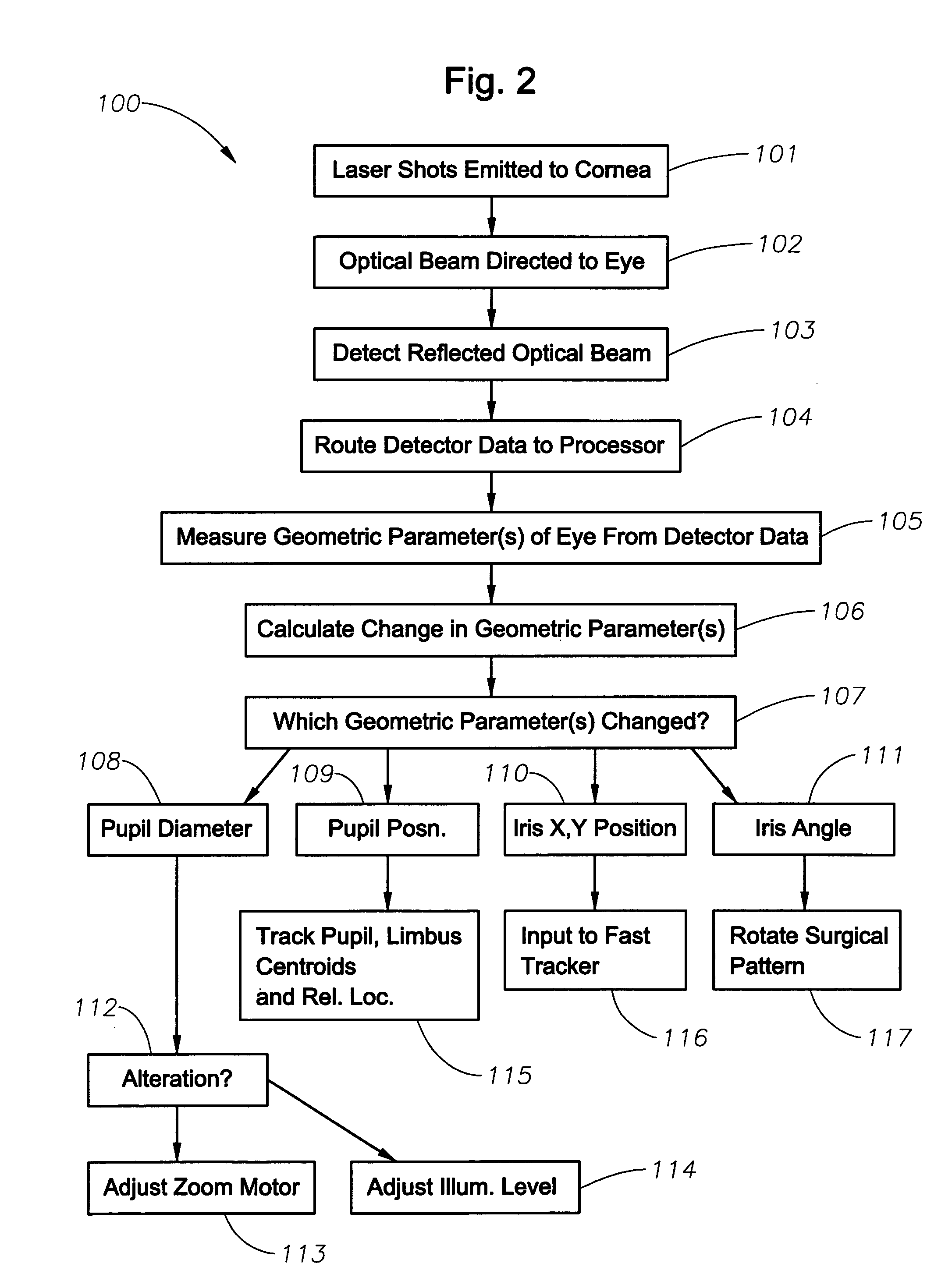
[0019] A system 10 (FIG. 1) and method 100 (FIG. 2) for performing a corrective procedure upon an undilated, unparalyzed eye are provided. The system 10 comprises a surgical component 11 and a tracking component, which in turn comprises a rapid eye movement (saccadic) tracker 12, such as disclosed in the '513 patent, and a slow movement tracker 13. The tracking components 12,13 are for tracking ocular changes during the surgical procedure.

[0020] The surgical component 11 comprises an ablating laser 14 and associated optics 15 adapted for emitting laser beam shots at a cornea 91 of an eye 90 in a predetermined pattern (block 101) based upon, for example, a wavefront measurement, although this is not intended as a limitation. The surgical component 11 is under control of a beam translation component 16 that is in turn under control of a processor 17 having sof...


PUM


Abstract

A system and method for tracking ocular changes during a surgical procedure include directing an eye-safe optical beam toward an undilated, unparalyzed eye. A reflected optical beam is detected, and measurements are performed based upon data contained in the reflected optical beam of at least one geometric parameter of the eye at a predetermined frequency, and from them is calculated a change in the at least one geometric parameter. The calculated change is used to dynamically adjust the directing of laser beam shots during the surgery.

Description

FIELD OF THE INVENTION [0001] The present invention relates to systems and methods for performing eye tracking, such as during laser surgery, and, more particularly, to such systems and methods for tracking both rapid and slow eye movements. DESCRIPTION OF RELATED ART [0002] The measurement of wavefront aberrations emanating from an eye is known in the art to provide data for driving laser-surgical corrective systems. Various embodiments of a method and system for objectively measuring and surgically correcting aberrations of optical systems by wavefront analysis have been disclosed in commonly owned application Ser. No. 09 / 566,668, “Apparatus and Method for Objective Measurement and Correction of Optical Systems Using Wavefront Analysis,” filed May 8, 2000, and in commonly owned issued U.S. Pat. Nos. 5,632,742 and 5,980,513, all of which are hereby incorporated by reference herein. [0003] Corrective laser surgery may be performed, for example, by laser ablation of portions of the c...

Claims


Application Information

Patent Timeline
IPC IPC(8): A61B18/20A61F9/008A61F9/01
CPCA61B18/20A61B2018/00636A61F2009/00872A61F9/00804A61F2009/00846A61F9/008A61F9/00
Inventor GRAY, GARY P.CAMPIN, JOHN A.BOTT, STEVEN E.GIBBS, DAVID M.PETTIT, GEORGE H.
Owner ALCON REFRACTIVEHORIZONS
Why Eureka
Try Eureka