Work table

Inactive Publication Date: 2005-06-30
FERTIGUNGSTECHN WEISSENFELS
View PDF11 Cites 0 Cited by
  • Summary
  • Abstract
  • Description
  • Claims
  • Application Information

AI Technical Summary

Benefits of technology

[0011] The basic object of the present invention is to improve a work table of the type described in the introduction such that the clamping will be reliably preserved even in case of failure of the energy supply, especially the pressurizing agent supply (fail-safe behavior).
[0016] An additional actuating member, which further boosts the locking force applied by the restoring member, is preferably provided. This would be especially suitable when the workpiece mounted on the work table is exposed to especially strong machining forces. Even though the locking force is reduced to the locking force applied solely by the restoring member in case of a failure of the rest of the actuating member, this force is sufficient to allow sufficient time for the human operator or the electronic system for an emergency shut-off of the machining, without a dangerous rotation of the workpiece mount occurring during this time.

Problems solved by technology

These forces apply a considerable torque on the round table, so that it may inadvertently rotate in relation to the housing.
The drawback of this procedure is that the clamping is released in case of failure of the pressurizing agent supply for the hydraulic cylinders.
This may lead to an inadvertent rotation of the round table and consequently to a crash of the workpiece and even to a risk of injury to personnel due to breaking tools and / or workpieces.

Method used


Image

  • Work table
  • Work table
  • Work table

Examples


Embodiment Construction

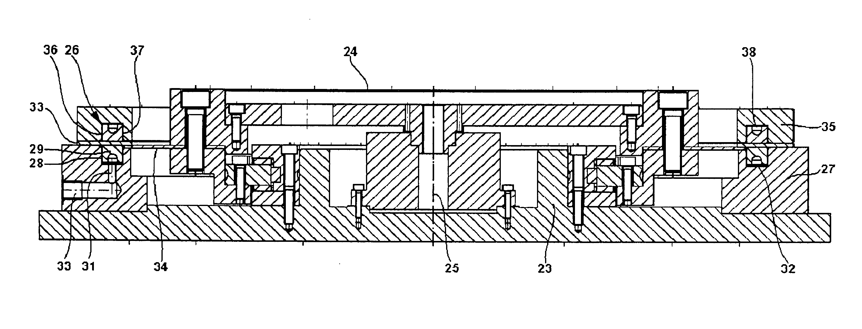
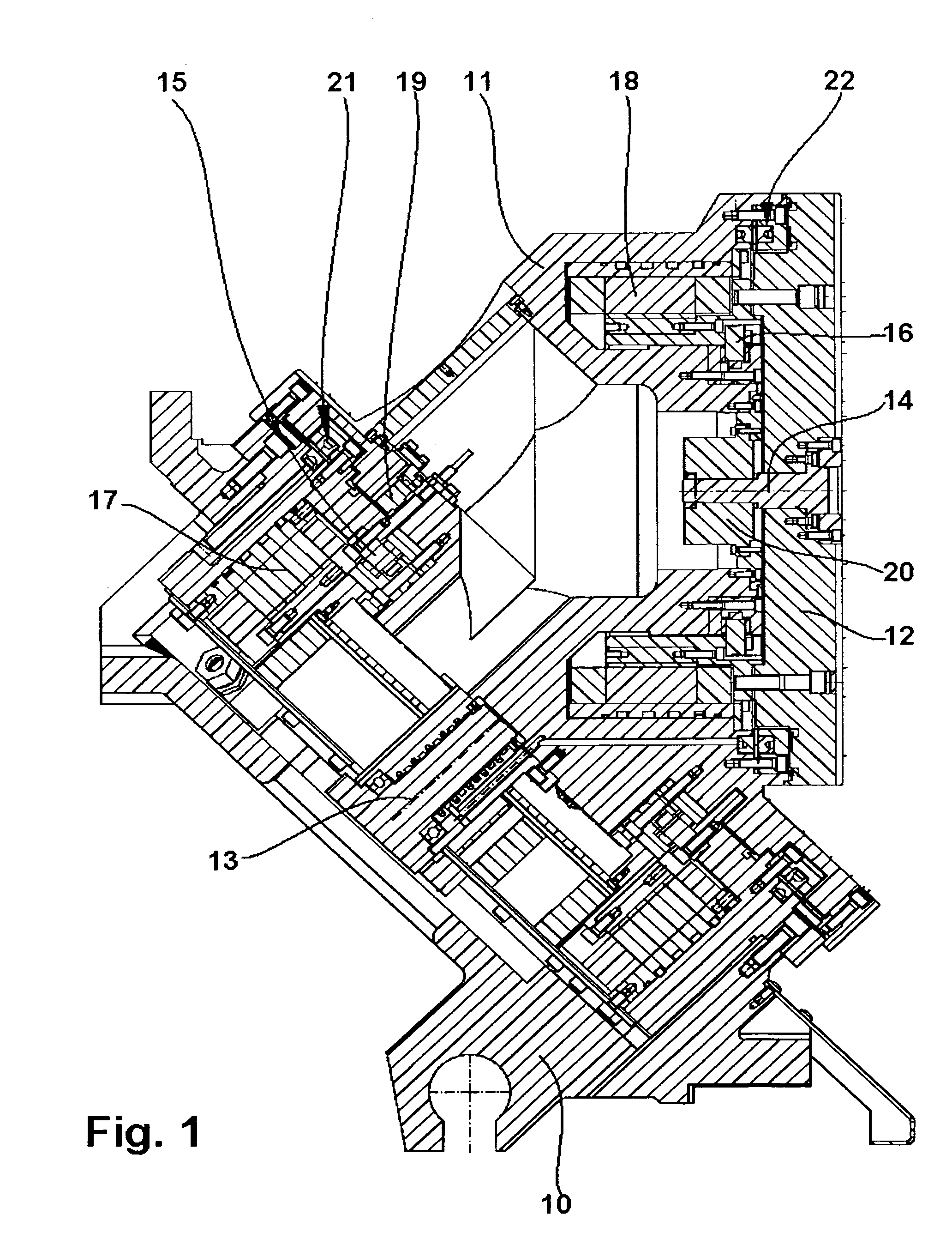
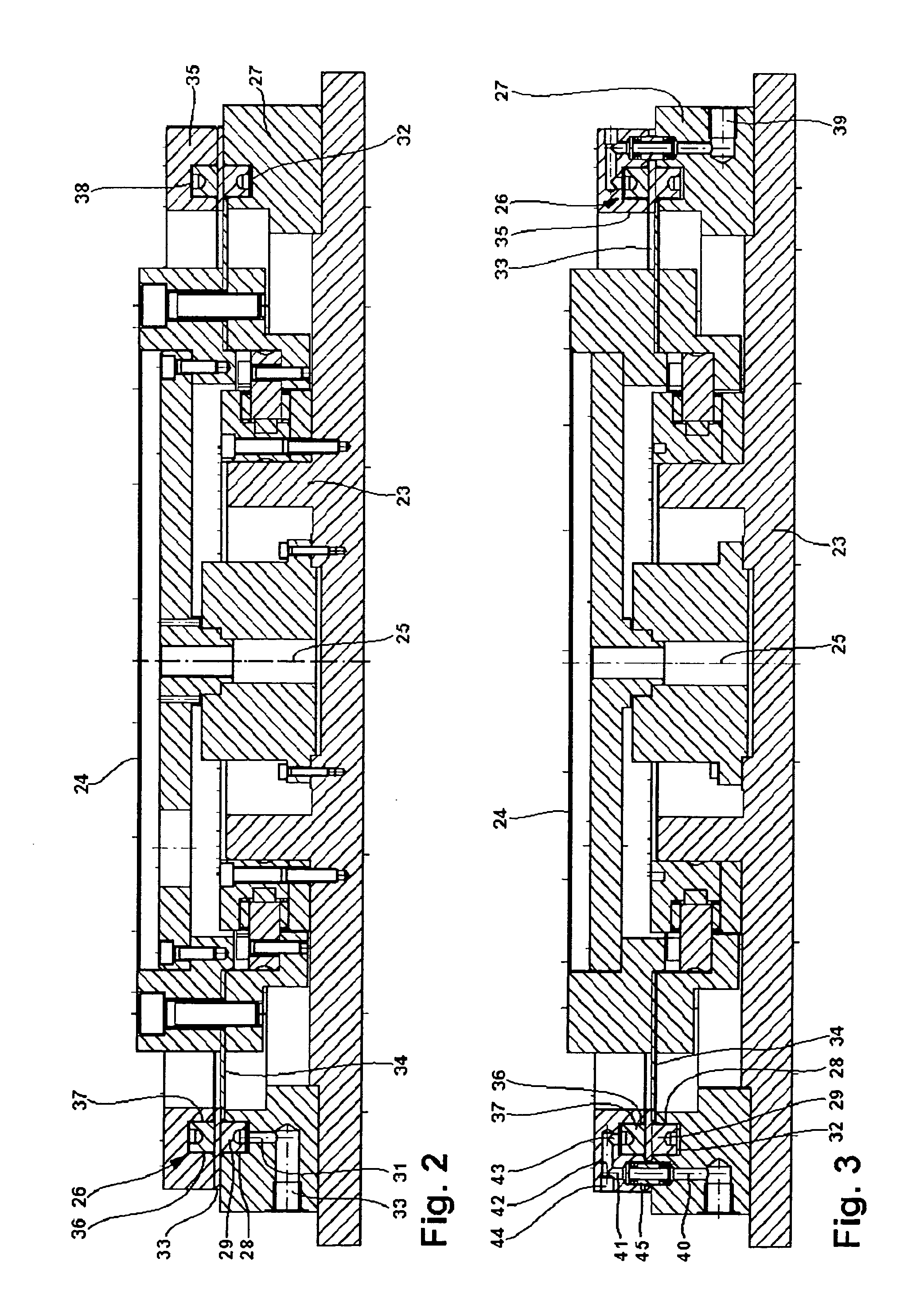
[0024] Referring to the drawings in particular, the work table shown in FIG. 1 has a housing 10 and, as a first rotary element, a pivoting housing 11 mounted rotatably at the housing 10. A face plate 12, at which workpieces can be mounted for machining in the known manner, is mounted rotatably as an additional rotary element at the pivoting housing 11. The pivoting housing 11 is rotatable around a first pivot axis 13 in relation to the housing 10, and the face plate 12 is rotatable around a second pivot axis 14 positioned at an angle in relation to the first pivot axis 13 in relation to the pivoting housing 11. The pivoting housing 11 is mounted at the housing 10 and the face plate 12 is mounted at the pivoting housing 11 by means of prior-art pivot bearings 15 and 16. A respective torque motor 17 and 18 is used as the rotating drive. The particular angular position of the pivoting housing 1 in relation to the housing 10 can be detected by means of a measuring system 19. Another mea...


PUM


Abstract

A work table is provided with a housing (10, 23) and a rotary element (11, 12, 24) mounted rotatably at the housing (10, 23) as well as with a locking device (22, 23, 26) for fixing the particular angle of rotation position of the rotary element (11, 12, 24) in relation to the housing (10, 23). To provide the work table with a fail-safe behavior the locking device (22, 23, 26) is released by a first actuating member when the energy supply is switched on and is activated by means of a restoring member when the energy supply is switched off. An additional actuating member may be provided to boost the locking force.

Description

CROSS REFERENCE TO RELATED APPLICATIONS [0001] This application claims the benefit of priority under 35 U.S.C. § 119 of German Application DE 103 58 943.0-14 filed Dec. 15, 2003, the entire contents of which are incorporated herein by reference. FIELD OF THE INVENTION [0002] The present invention pertains to a work table with a housing and with a rotary element mounted rotatably at the housing as well as with a locking means for fixing the particular angle of rotation position of the rotating element in relation to the housing. BACKGROUND OF THE INVENTION [0003] Such a work table is disclosed, for example, in DE 202 02 998 U1. This work table has a round table mounted rotatably at a housing, which is called substructure in the document. Workpieces are clamped on the round table in the usual manner in order to subject them to machining, especially cutting. Consequently, the round table is a workpiece mount arranged rotatably at the housing. The workpieces mounted on the round table c...

Claims


Application Information

Patent Timeline
IPC IPC(8): B23Q1/25B23Q1/26B23Q1/28B23Q1/50B23Q16/10
CPCB23Q1/26Y10T74/20341B23Q16/102
Inventor BURKHARDT, CARSTENMARKUS, HARTMUT
Owner FERTIGUNGSTECHN WEISSENFELS
Why Eureka
Try Eureka