Container for holding a cryogenic fluid

a technology for cryogenic fluids and containers, applied in the direction of containers, transportation and packaging, discharging methods, etc., can solve the problem of too much heat leakage, achieve the effect of reducing radiant and convective heat transfer, reducing heat leakage into the cryogenic space, and reducing thermal conductivity

Active Publication Date: 2005-06-30
WESTPORT FUEL SYST CANADA INC
View PDF40 Cites 19 Cited by
  • Summary
  • Abstract
  • Description
  • Claims
  • Application Information

AI Technical Summary

Benefits of technology

[0041] A method is provided of supporting an inner vessel that defines a cryogen space within an outer vessel, and transferring axial and radial loads between the inner vessel and the outer vessel while reducing heat leak into the cryogen space. The axial loads are transferable in a direction parallel to an elongated horizontal axis of the inner vessel and the radial loads are transferable in a radial direction perpendicular to the horizontal axis. The method comprises evacuating a sealed space between the inner vessel and the outer vessel, transferring substantially all loads in the radial direction through at least one non-metallic structural member that has a lower thermal conductivity than a ferrous material with at least the same strength in the radial direction, transferring a substantial portion of loads in the axial direction through a conduit, and transferring a substantial portion of loads in the axial direction through the at least one non-metallic structural member. The at least one non-metallic structural member can be one of two non-metallic structural members, through which substantially all loads in the radial direction are transferred.
[0042] The method can further comprise wrapping the inner vessel with a super insulating material to reduce radiant and convective heat transfer.
[0043] The method can further comprising allowing the inner vessel to move in the axial direction relative to the outer vessel. This is a feature that has utility for containers that have a long horizontal axis. For smaller vessels the amount of stress caused by differential thermal expansion can be negligible, and it is possible to rigidly attach each end of the inner vessel along the horizontal axis to the outer vessel if more support in the axial direction is required from the non-metallic supports. The method comprises fixedly attaching at least one non-metallic structural member to the inner and outer vessel with an adhesive or with a mechanical joint, or with a combination of adhesives and mechanical joints.

Problems solved by technology

The wall thickness of the conduit would have to be much greater to provide a substantial amount of support in the radial direction and this would cause too much heat leak.

Method used


Image

  • Container for holding a cryogenic fluid
  • Container for holding a cryogenic fluid
  • Container for holding a cryogenic fluid

Examples


Embodiment Construction

)

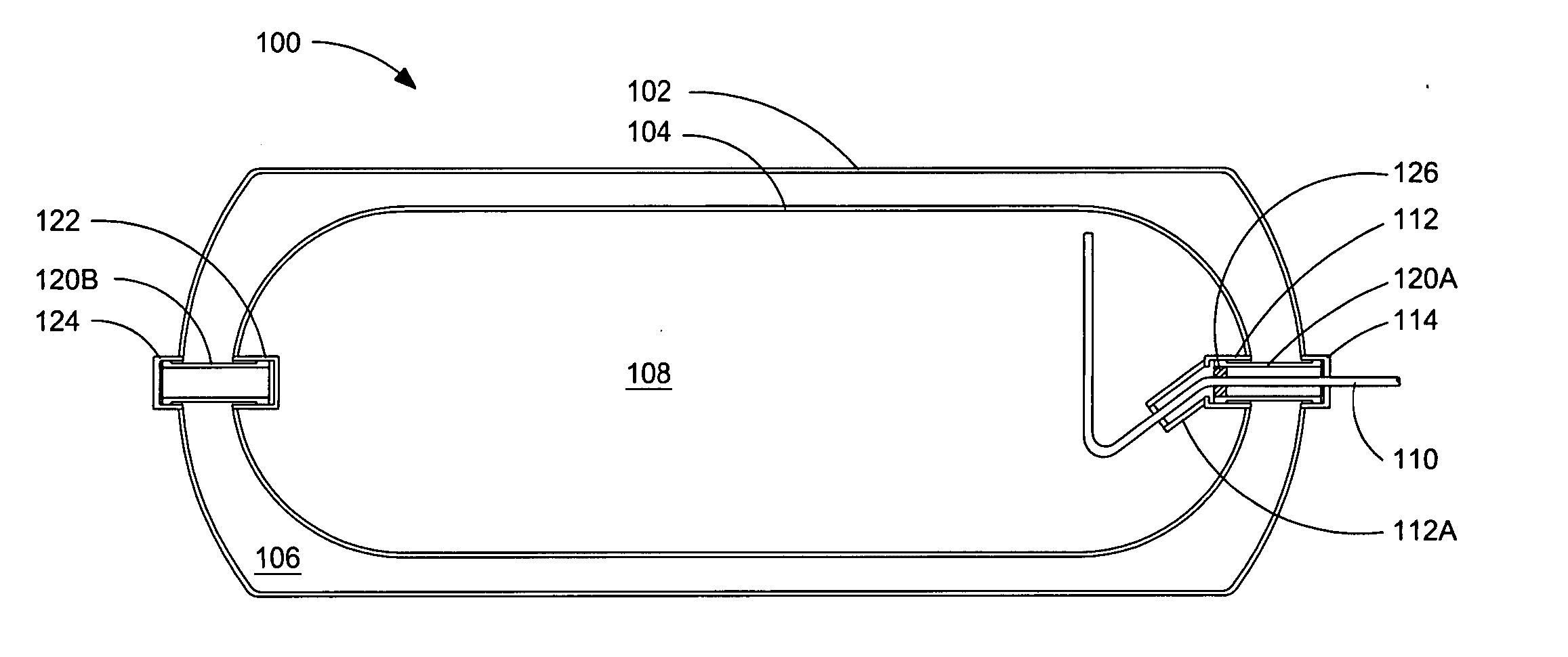
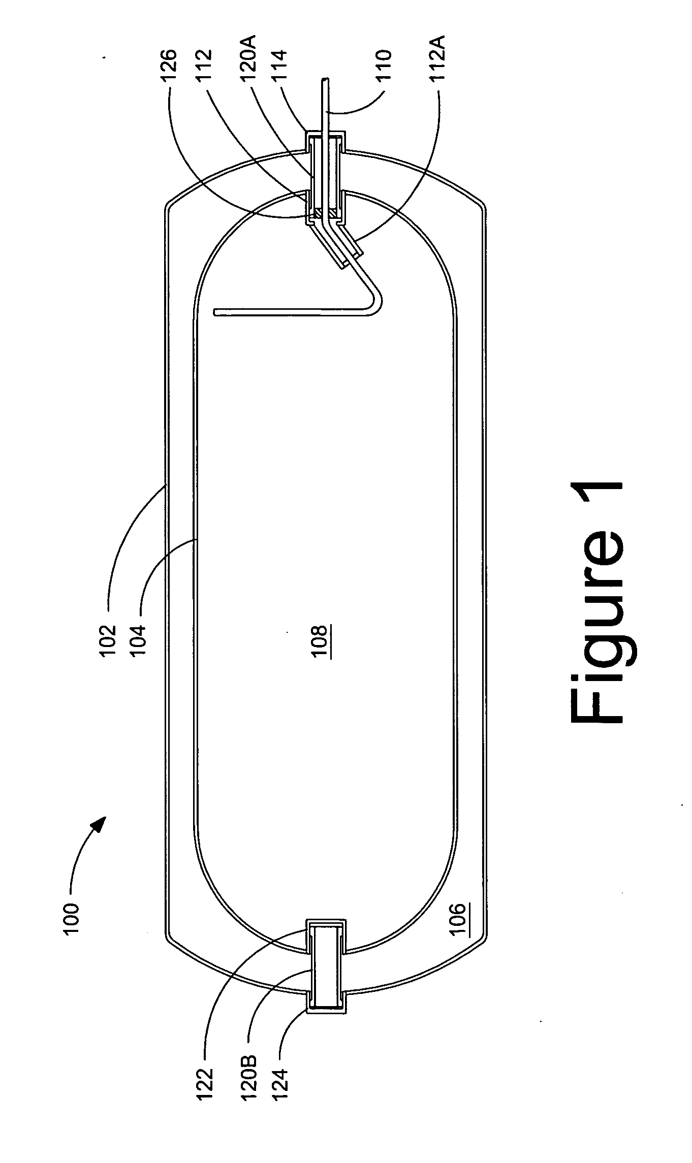
[0049]FIG. 1 is a cross-sectional view of a heat insulated double-walled container 100 for holding a cryogenic fluid. Outer vessel 102 surrounds, and is spaced apart from, inner vessel 104, defining evacuatable space 106 therebetween. Inner vessel 104 also defines the general boundaries of cryogen space 108. In the illustrated embodiment, inner vessel 104 has a cylindrical body with dome-shaped ends. This shape conforms with the general shape of conventional fuel tanks attached to heavy-duty trucks. In the present container for holding a cryogenic fluid, the support system for inner vessel 104 and other shapes could be employed for the inner vessel with the same support system. For example, other shapes such as a sphere or an elongated vessel with an elliptical cross-section can be dictated by the application and the space available for mounting the container. For strength reasons, rounded shapes are preferred compared to shapes with sharp or square corners.

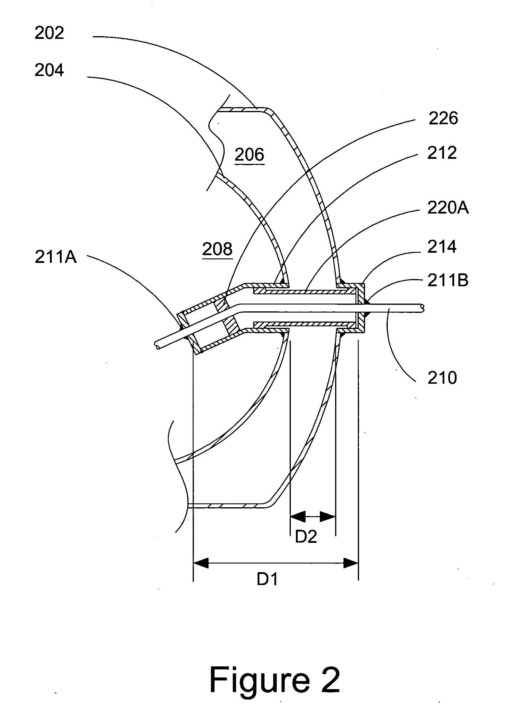
[0050] As shown in FIG....


PUM

PropertyMeasurementUnit
cure temperatureaaaaaaaaaa
temperaturesaaaaaaaaaa
shapeaaaaaaaaaa

Abstract

A double-walled vacuum-insulated container for holding a cryogenic fluid comprises a support structure for supporting an inner vessel within an outer vessel. The container has an elongated horizontal axis. A conduit extending between the inner and outer vessels has a wall thickness that allows the conduit to carry a substantial portion of axial loads acting on the inner vessel in a direction parallel to the horizontal axis. The support structure further comprises a non-metallic support spanning between the inner and outer vessels, with the non-metallic support capable of transferring substantially all radial loads transverse to said horizontal axis. The non-metallic support is also fixedly attached to the inner and outer vessels so that it is capable of supporting a substantial portion of the axial loads so that the non-metallic support and the conduit cooperate to provide support in the axial direction.

Description

FIELD OF THE INVENTION [0001] The present invention relates to a container for holding a cryogenic fluid. More particularly, this invention relates to a heat insulated double-walled container with a combined support and fluid conduit structure for suspending an inner vessel within an outer vessel, for reducing heat transfer and allowing longer holding times. BACKGROUND OF THE INVENTION [0002] Developments in combustion engine technology have shown that compression ignition engines, frequently referred to as diesel-cycle engines, can be fuelled by gaseous fuels instead of diesel without sacrifices in performance or efficiency. Examples of such fuels include natural gas, methane, propane, ethane, gaseous combustible hydrocarbon derivatives, hydrogen, and blends thereof. Substituting diesel with such gaseous fuels generally results in cost, availability and emissions benefits over diesel. [0003] However, one challenge in using gaseous fuels for such applications is that the energy dens...

Claims


Application Information

Patent Timeline
Patent Type & Authority Applications(United States)
IPC IPC(8): F17C1/00
CPCF17C2201/0109Y10S220/901F17C2201/035F17C2201/056F17C2203/0304F17C2203/0391F17C2203/0629F17C2203/0636F17C2203/0643F17C2203/0673F17C2205/0323F17C2205/0332F17C2205/0352F17C2205/0382F17C2205/0394F17C2209/221F17C2209/224F17C2209/227F17C2209/228F17C2221/011F17C2221/012F17C2221/014F17C2221/017F17C2221/033F17C2221/035F17C2223/0161F17C2223/033F17C2223/043F17C2225/043F17C2227/0135F17C2250/0408F17C2260/011F17C2260/033F17C2260/044F17C2265/066F17C2270/0171Y02E60/321F17C1/00F17C2203/014F17C2201/0128B65D77/04B65D81/38F17C1/12F17C3/02B65D77/0493B65D81/3806Y02E60/32
Inventor HARPER, GREGORY C.GISH, JUSTIN
Owner WESTPORT FUEL SYST CANADA INC
Why Eureka
Try Eureka