
Rear wheel suspension apparatus

a rear wheel and suspension technology, applied in resilient suspensions, interconnection systems, vehicle components, etc., can solve the problems of large reaction force, difficult to produce a flat and wide inside space in the passenger compartment and trunk, and difficult to effectively block the transmission of vibrations to the passenger compartment, etc., to achieve wide passenger room space, improve vibration characteristics, and facilitate the effect of providing

Inactive Publication Date: 2005-06-30
MORGAN LEWIS & BOCKIUS
View PDF10 Cites 11 Cited by
  • Summary
  • Abstract
  • Description
  • Claims
  • Application Information

AI Technical Summary

Benefits of technology

[0007] An embodiment of the present invention provides a rear wheel suspension apparatus in which a shock absorber and a spring are separately mounted, vibration characteristics are improved by regulating the geometry of transverse arms, and it becomes easier to provide a wide passenger room space and a wide trunk space.

Problems solved by technology

However, in such a conventional rear wheel suspension apparatus, the shock generated by the vehicle driving on a road's surface is concentrated on the mounting strut, where a huge reactional force is generated.
In addition, routes for transmitting vibrations are concentrated on the mounting strut, so it is difficult to effectively block the transmission of vibrations to the passenger compartment.
Furthermore, the spring and shock absorber assembly protrudes into the vehicle's interior, making it difficult to produce a flat and wide inside space in the passenger compartment and in the trunk.

Method used


Image

  • Rear wheel suspension apparatus
  • Rear wheel suspension apparatus
  • Rear wheel suspension apparatus

Examples


Embodiment Construction

[0019] Hereinafter, a preferred embodiment of the present invention will be described in detail with reference to the accompanying drawings.

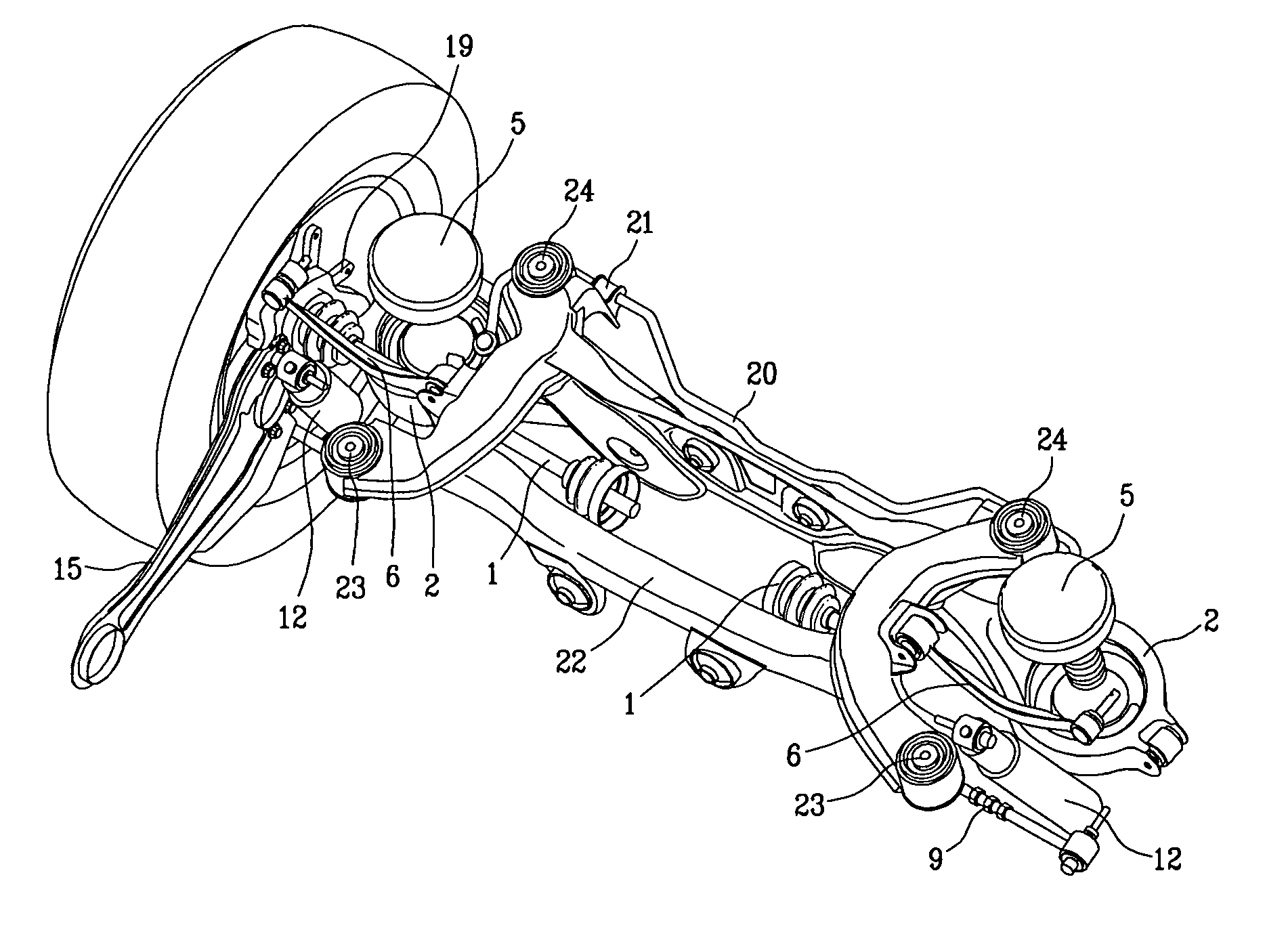
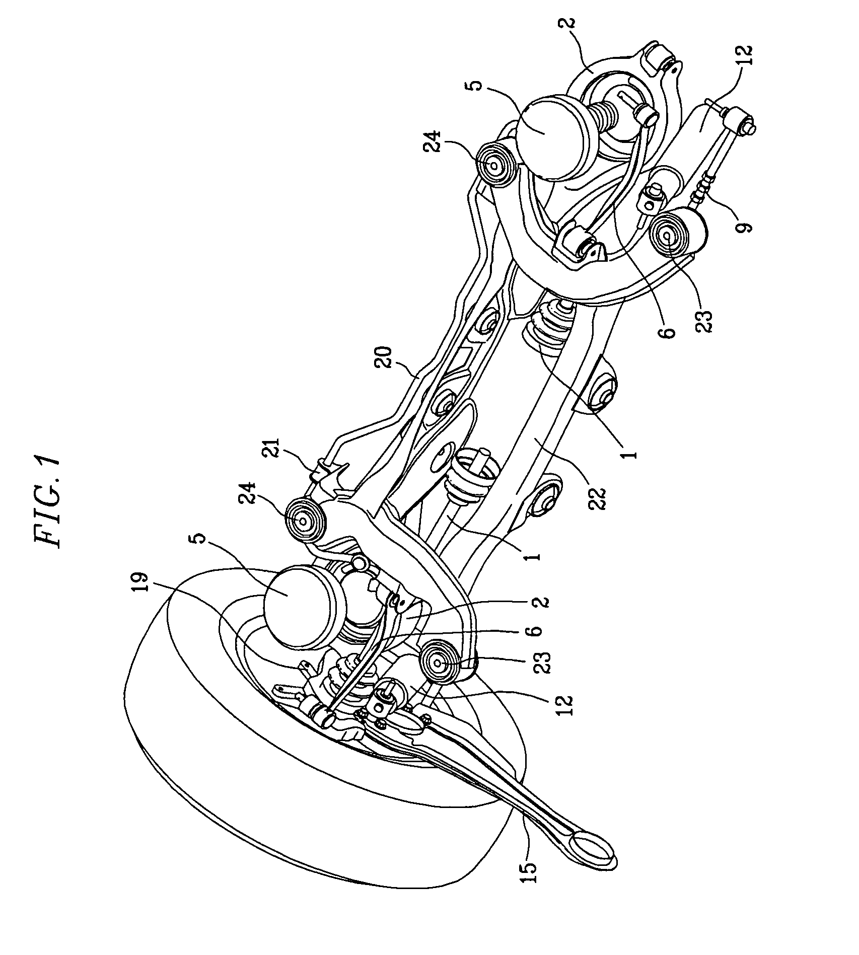
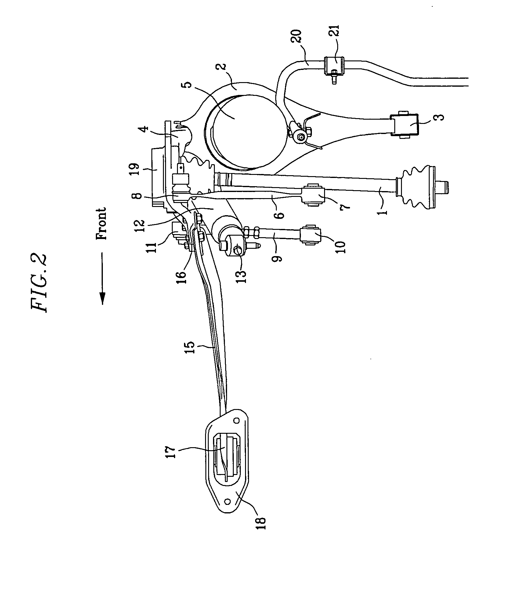
[0020] As shown in FIGS. 1 through 4, a rear wheel suspension apparatus according to an embodiment of the present invention comprises a transverse lower arm 2, a transverse compensating arm 9, a transverse upper arm 6, and a longitudinal arm 15.

[0021] The transverse upper arm 6 is positioned ahead of the transverse lower arm 2, and one end of each of the transverse lower arm 2, the transverse compensating arm 9, and the transverse upper arm 6 are connected to a carrier 19. As shown in FIG. 3, the longitudinal arm 15 is rotatably connected to a bracket 18 that is fixed to a vehicle body. Therefore, the longitudinal arm 15 is rotatably connected to the vehicle body. The bracket 18 can be eliminated depending on the shape of the vehicle body, and it is also possible that the longitudinal arm 15 can be directly connected to the vehicle body.

[0022...


PUM


Abstract

A rear wheel suspension apparatus for a vehicle is provided, comprising: a carrier to which a wheel is mounted; a plurality of arms comprising a transverse lower arm connecting the carrier to a sub-frame, a transverse compensating arm, a transverse upper arm, and a longitudinal arm; a spring providing an elastic force; and a shock absorber. The transverse upper arm is positioned ahead of the transverse lower arm. The spring is located on the transverse lower arm. A lower fixing eye of the shock absorber is connected to the carrier at a position lower than a link point between the carrier and the transverse lower arm. An upper portion of the shock absorber is connected to a side portion of a vehicle frame.

Description

CROSS REFERENCE TO RELATED APPLICATIONS [0001] This application claims priority from Korean Application No. 10-2003-0100933, filed on Dec. 30, 2003, which is incorporated herein by reference in its entirety. FIELD OF THE INVENTION [0002] The present invention relates to a suspension system for a vehicle, and more particularly, to a multi-link type rear wheel suspension system for a vehicle. BACKGROUND OF THE INVENTION [0003] Generally, in the conventional rear wheel suspension apparatus of a vehicle, the ends of a plurality of transverse arms are connected to a carrier to which a wheel is coupled, and the other ends of the plurality of transverse arms are connected to an auxiliary frame that extends in a transverse direction of the vehicle. One end of a longitudinal arm is connected to the carrier, and the other end of the longitudinal arm is connected to a vehicle body. In addition, a spring and shock absorber assembly, in which a spring and a shock absorber are formed integrally, ...

Claims


Application Information

Patent Timeline
IPC IPC(8): B60G7/00B60G3/20B60G9/00B60G11/00B60G13/08B60G15/00B60G21/055B62D21/00
CPCB60G2200/1442B60G3/202B60G9/00
Inventor KIM, HYUK
Owner MORGAN LEWIS & BOCKIUS
Learn More