Overheat protection device for movable body surface, overheat protection apparatus using the same and temperarture control device

a technology of overheating protection device and movable body, which is applied in the direction of emergency protection device, ohmic resistance heating, electrical apparatus, etc., can solve the problems of preventing the function of thermally protecting the subject of detection and ensuring sufficient safety, and the temperature of the thermal fuse is greatly different from that of the subject of detection, so as to achieve the effect of preventing thermal damage to the movable body and high response to a temperature chang

Inactive Publication Date: 2005-06-30
FUJIFILM BUSINESS INNOVATION CORP
View PDF6 Cites 41 Cited by
  • Summary
  • Abstract
  • Description
  • Claims
  • Application Information

AI Technical Summary

Benefits of technology

[0012] The present invention has been made in consideration of the above situation, and provides an overheat protection device which has a high response to a temperature change even if the temperature of a movable body as a subject of detection rises radically, and which prevents a general accident due to abnormal temperature rise and prevents thermal damage to the movable body itself by reducing the difference between the temperature of itself and that of the surface of the movable body as much as possible under abnormal conditions. An overheat protection apparatus using the overheat protection device is also provided.

Problems solved by technology

However, there is a possibility that such temperature control unit operates abnormally due to a trouble or break in circuit parts of an internal control circuit.
However, in a case where the temperature of the subject of detection rapidly rises, the temperature of the thermal fuse is greatly different from that of the subject of detection.
In such a case, an influence on a user and peripheral devices can be prevented, but there is a possibility that the function of thermally protecting the subject of detection and ensuring sufficient safety cannot be performed.
Further, in a case where the subject of detection is a movable body such as a rotary member, since it is generally impossible to bring the thermal fuse into direct contact with the subject of detection, the thermal fuse is provided with an interval from the subject of detection.
In this case, there is no thermal conduction from the subject of detection and the thermal response of the thermal fuse is not excellent.
Accordingly, in some cases, when the thermal fuse is actuated, the temperature of the subject of detection has already reached a temperature to cause thermal damage.
In such a case, the problem is noticeable in the response of the thermal fuse when the temperature of the rotary heating body as a subject of detection is greatly different from that of the thermal fuse.

Method used


Image

  • Overheat protection device for movable body surface, overheat protection apparatus using the same and temperarture control device
  • Overheat protection device for movable body surface, overheat protection apparatus using the same and temperarture control device
  • Overheat protection device for movable body surface, overheat protection apparatus using the same and temperarture control device

Examples


first embodiment

[0036] Hereinbelow, a first embodiment as an example of an overheat protection device according to the present invention will be described. In the overheat protection device of the embodiment, a thermal fuse of substrate type is employed.

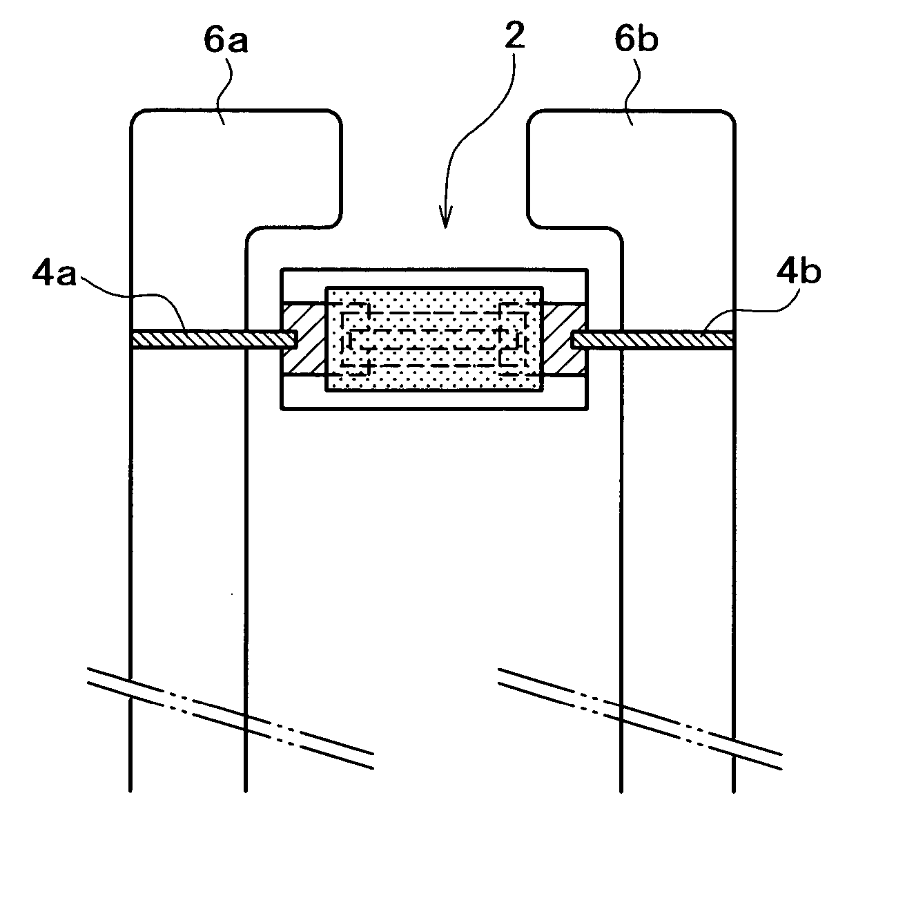
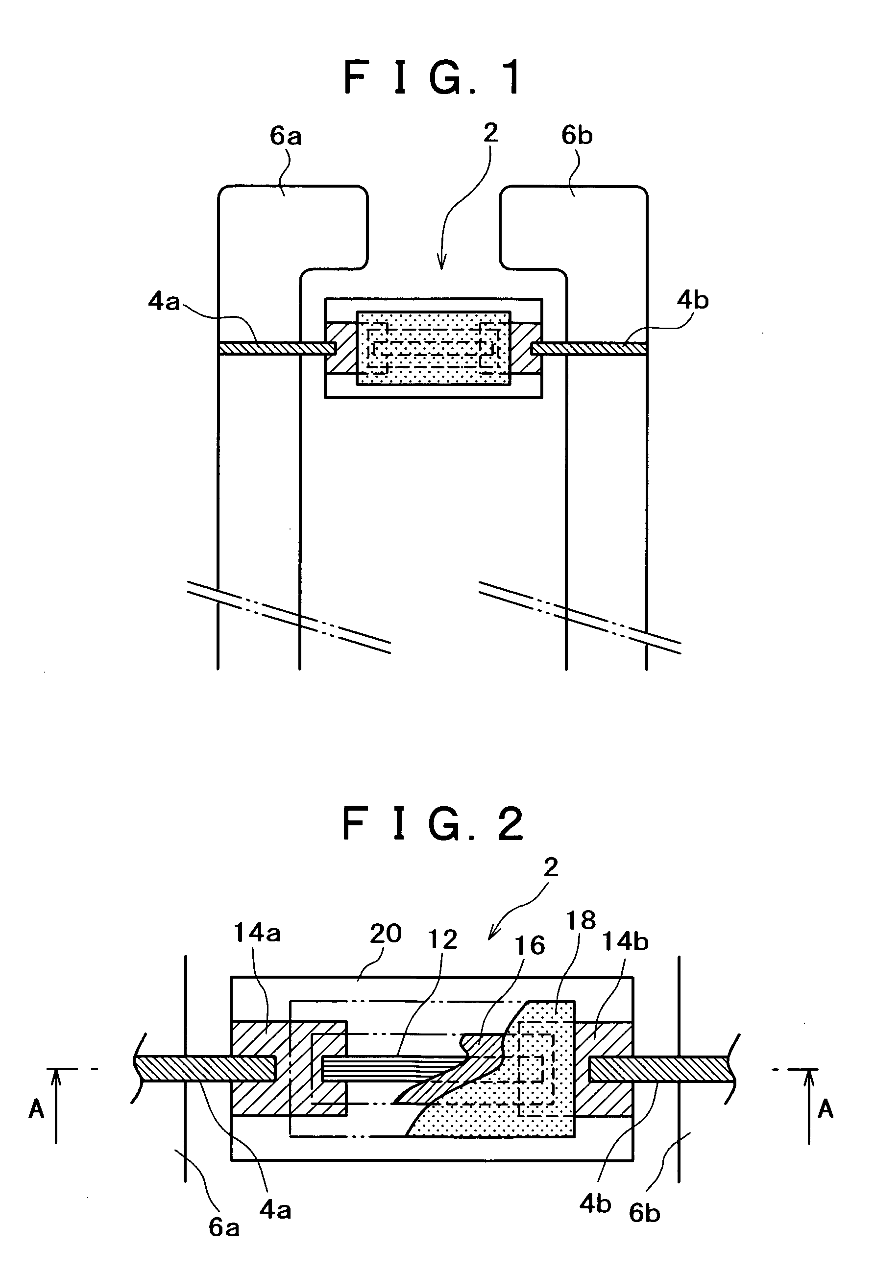
[0037]FIG. 1 is a plan view showing principal parts of the overheat protection device according to the embodiment. As shown in FIG. 1, in the overheat protection device, a fusible alloy thermal fuse (thermal fuse) 2 is electrically connected with peripheral portions of ends of a pair of long metal spring plates (plate elastic bodies) 6a and 6b via leads 4a and 4b, such that the thermal fuse bridges the pair of spring plates.

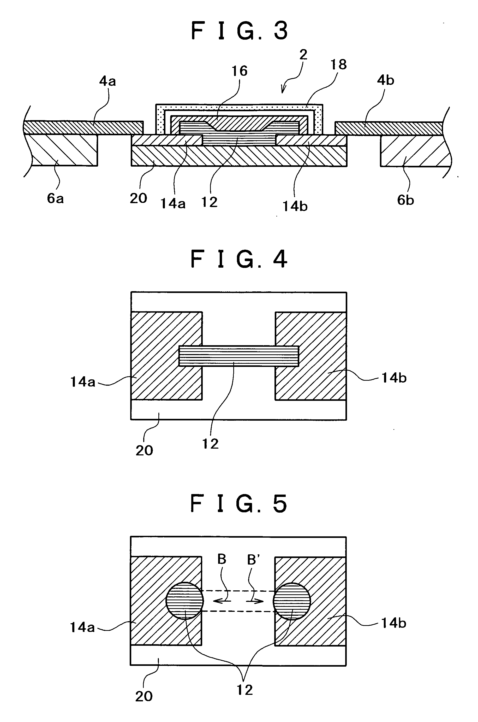
[0038]FIG. 2 is an expanded plan view showing the periphery of the fusible alloy thermal fuse 2 in the overheat protection device according to the embodiment. FIG. 3 is a cross-sectional view along a line A-A in FIG. 2. Note that in FIG. 2, some members are cut, and portions that would exist if not cut, or portions hidden with ...

second embodiment

[0098] Next, a second embodiment will be described as another example of the overheat protection device according to the present invention. In the overheat protection device of this embodiment, a cylindrical type fuse is employed as the thermal fuse.

[0099]FIG. 12 is a plan view showing principal parts of the overheat protection device according to this embodiment. FIG. 13 is a cross-sectional view along a line G-G in FIG. 12. As shown in FIGS. 12 and 13, in the overheat protection device according to this embodiment, a fusible alloy thermal fuse (thermal fuse) 72 is electrically connected with peripheral portions of ends of a pair of long metal spring plates (plate elastic bodies) 6a and 6b via leads (as a pair of electrodes) 64a and 64b, such that the thermal fuse bridges the pair of spring plates.

[0100] In the fusible alloy thermal fuse 72, the pair of leads 64a and 64b having round ends and cross section are arranged such that the end portions having a function of electrode are...

third embodiment

[0114] Finally, a third embodiment as an example of the temperature control device according to the present invention will be described. The temperature control device according to this embodiment is constructed by use of the overheat protection device of the first embodiment.

[0115]FIG. 15 is a perspective view showing the temperature control device according to this embodiment. In FIG. 15, constituent elements and functions the same as those of the overheat protection device of the first embodiment have the same reference numerals as those in FIG. 6 and the detailed explanations thereof will be omitted.

[0116] In FIG. 15, in the overheat protection device 30, the ends of the metal spring plates 6a and 6b opposite to the ends connected with the fusible alloy thermal fuse 2 are held with a holding member 92, and the external leader lines 24 electrically connected with the metal spring plates 6a and 6b are connected with the break control circuit (not shown), as in the case of the fi...


PUM


Abstract

An overheat protection device for a movable body surface includes a thermal fuse having a fuse element which melts at a predetermined temperature, bridges electrodes in a pair and melts at a temperature equal to or higher than the predetermined temperature to break an electrical connection between the pair of electrodes, and a pair of long elastic bodies, to each of which one of the electrodes is electrically connected at an end or its periphery of the elastic body through a lead. At least one of pairs of upper surfaces and lower surfaces of the elastic bodies are spatially on a same plane.

Description

BACKGROUND OF THE INVENTION [0001] 1. Field of the Invention [0002] The present invention relates to an overheat protection device used for prevention of overheating of the surface of a movable body, which is heated by a heating device while temperature control is performed on the surface, an overheat protection apparatus, and a temperature control device having a function as a temperature detection device for temperature control in addition to a function of such overheat protection. [0003] 2. Description of the Related Art [0004] Conventionally, some electronic devices, electric heaters, heat exchangers and the like (e.g., water heaters and air heating apparatuses) detect the temperature in a predetermined position with a temperature sensor for temperature control. These devices are provided with a temperature control unit to stop energization or combustion when the detected temperature has exceeded a target temperature. However, there is a possibility that such temperature control...

Claims


Application Information

Patent Timeline
Patent Type & Authority Applications(United States)
IPC IPC(8): H01H37/76H05B3/00
CPCH01H37/761
Inventor UEHARA, YASUHIROITOH, KAZUYOSHI
Owner FUJIFILM BUSINESS INNOVATION CORP
Why Eureka
Try Eureka