Plasma display panel driving method

a technology of plasma display panel and driving method, which is applied in the direction of racket sports, golf clubs, instruments, etc., can solve the problems of no external voltage supplied between the address electrode and the y electrode, the charge marked with circles on the x and y electrodes is not useful in sustaining the voltage difference between the x and y electrodes, and the current restriction resistor is not used, so as to reduce the voltage v′w, reduce the reset voltage vs

Inactive Publication Date: 2005-06-30
SAMSUNG SDI CO LTD
View PDF10 Cites 4 Cited by
  • Summary
  • Abstract
  • Description
  • Claims
  • Application Information

AI Technical Summary

Benefits of technology

[0028] It is an object of the present invention to provide a PDP driver and a PDP driving method that can reduce a reset voltage to use low-voltage elements and to achieve high contrast.
[0031] Thus, the present invention removes unnecessary negative charges stored in the X electrode and the Y electrode, and generates an internal voltage difference to provide a firing voltage between the address electrode and the Y electrode. Accordingly, the reset voltage may be lowered since less charge is required.
[0036] As expressed in Equation 2, since the present invention sustains the voltage difference of Vn between the address electrode and the Y electrode when terminating the reset operation, it can reduce the voltage V′w,ay caused by the wall charges accumulated at the address electrode and the Y electrode. Therefore, since less wall charges compared to the prior art can be stored in the address electrode, a lower reset voltage Vset can be used for driving operation.

Problems solved by technology

Since the DC PDPs have electrodes exposed in the discharge space, they allow the current to flow in the discharge space while the voltage is supplied, and therefore, they have a problem of requiring resistors for current restriction.
However, no external voltage is supplied between the address electrode and the Y electrode.
Referring to FIG. 4D, the charges marked with circles on the X and Y electrodes are not useful in sustaining the voltage difference between the X and Y electrodes.
Also, the conventional method generates high intensity of background light emission, rendering it difficult to achieve high contrast.

Method used


Image

  • Plasma display panel driving method
  • Plasma display panel driving method
  • Plasma display panel driving method

Examples


Embodiment Construction

[0048] In the following detailed description, only the preferred embodiments of the invention have been shown and described, simply by way of illustrating the best modes contemplated by the inventor(s) of carrying out the invention. As will be realized, the invention is capable of modification in various obvious respects, all without departing from the invention. Accordingly, the drawings and description are to be regarded as illustrative in nature, and not restrictive.

[0049]FIG. 6 shows PDP driving voltage waveforms according to a first preferred embodiment of the present invention.

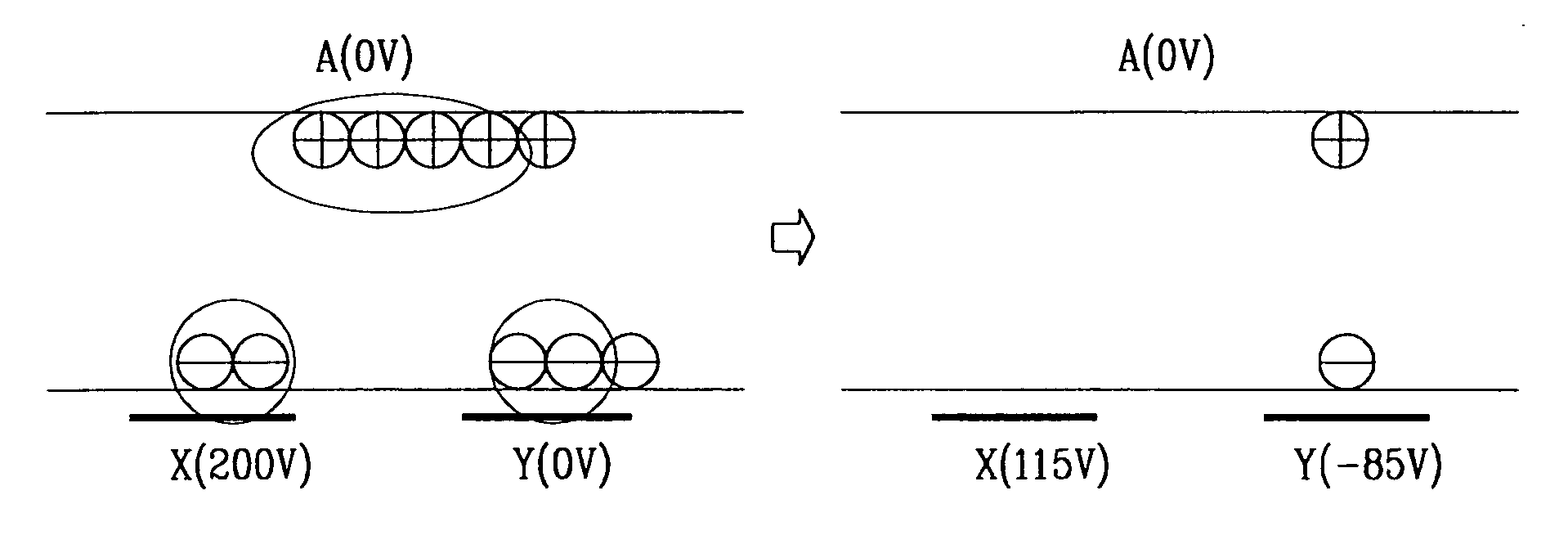
[0050] As shown, according to the first preferred embodiment of the present invention, the voltage at the Y electrode is lowered to less than the address voltage (ground voltage) in the falling ramp period. Accordingly, the difference (i.e., V′e+Vn) of the externally-received voltage at the X electrode and the Y electrode is sustained to be similar to the conventional voltage difference Ve. This provid...


PUM


Abstract

A PDP driving method that reduces the reset voltage of the PDP driving waveforms to make it possible to use low-voltage elements and to achieve high contrasts is disclosed. Since conventional PDP waveforms require very high reset voltages, it causes a problem of intense background light emissions, low contrasts, use of high-voltage components, and increased circuit costs. According to the driving waveforms of the present invention, relative voltage differences between the address electrode and the X electrode and between the X electrode and the Y electrode are considered to design waveforms of low reset voltages, thereby providing high contrasts and low-cost circuit.

Description

CROSS REFERENCE TO RELATED APPLICATION [0001] This application is based on U.S. Provisional Application No. 60 / 356,735 filed on Feb. 15, 2002, of which content is hereby incorporated by reference and the benefit of which filing date is hereby claimed.BACKGROUND OF THE INVENTION [0002] (a) Field of the Invention [0003] The present invention relates to a PDP (plasma display panel) driving method. More specifically, the present invention relates to a low voltage resetting PDP driving method. [0004] (b) Description of the Related Art [0005] Recently, flat displays such as LCDs (liquid crystal displays), FEDs (field emission displays), and PDPs have been widely developed. Among them, PDPs have higher luminance and wider viewing angles compared to other flat displays. Hence, PDPs have come into the spotlight as substitutes for conventional CRTs (cathode ray tubes) having screen sizes bigger than 40 inches. [0006] The PDP is a flat display for using plasma generated via a gas discharge pro...

Claims


Application Information

Patent Timeline
Patent Type & Authority Applications(United States)
IPC IPC(8): G09G3/288G09G3/20
CPCG09G3/282G09G3/288G09G3/292G09G2320/0238G09G2310/066G09G2320/0228G09G3/2927A63B53/047A63B60/52A63B2053/0479A63B53/0445
Inventor SEO, JEONG-HYUNLEE, JOO-YULKIM, TAE-HYUNKIM, HEE-HWANYOO, MIN-SUN
Owner SAMSUNG SDI CO LTD
Why Eureka
Try Eureka