Liquid crystal display apparatus

a display apparatus and liquid crystal technology, applied in static indicating devices, instruments, non-linear optics, etc., can solve the problems of disadvantageous ips display mode and variable color tones, and achieve the effect of restricting color tones variation

Inactive Publication Date: 2005-06-30
PANASONIC LIQUID CRYSTAL DISPLAY CO LTD +1
View PDF5 Cites 36 Cited by
  • Summary
  • Abstract
  • Description
  • Claims
  • Application Information

AI Technical Summary

Benefits of technology

[0010] Further, the means reported in JP-A-9-297299 specification desirably sets a retardation deff·Δneff at a small value of 250 nm or less (where deff denotes an effective thickness of the liquid crystal layer and Δneff denotes an effective refractive-index anisotropy of the liquid crystals). This setting requires a gap and the refractive-index anisotropy to be reduced. A reduction in the gap may lower productivity, while a reduction in refractive-index anisotropy narrows the range of liquid crystals any of which are to be selected. Thus, solving these problems requires a means that does not substantially restrict the retardation.
[0011] It is an object of the present invention to provide a liquid crystal display apparatus having a new configuration and which restrains a variation in color tones on a display panel depending on a driving voltage without any unreasonable restrictions on retardation, using only the liquid crystal panel.

Problems solved by technology

There are now needs for a display monitor that can reliably reproduce colors, but the above described IPS display mode is disadvantageous in that color tones vary depending on a driving voltage.

Method used


Image

  • Liquid crystal display apparatus
  • Liquid crystal display apparatus
  • Liquid crystal display apparatus

Examples


embodiment 1

[Embodiment 1]

[0076] The configuration of Embodiment 1 of the present invention will be described with reference to FIGS. 3A, 3B, and 4. FIGS. 3A and 3B are views useful in explaining the configuration of a pixel portion, and FIG. 4 is a view useful in explaining a driving system for a liquid crystal display apparatus. More specifically, FIG. 3B is a bird's eye view useful in explaining the configuration of a pixel 41 on a substrate 1, FIG. 3A is a sectional view taken along line A-A′ in FIG. 3B, and FIG. 4 is a view useful in explaining a configuration for wiring on the substrate 1.

[0077] A liquid crystal display apparatus of this embodiment has a configuration described below.

[0078] As shown in FIGS. 3A and 3B, the apparatus has a substrate 1, a substrate 2, a liquid crystal layer 12 sandwiched between the substrates 1 and 2 and having a positive dielectric anisotropy, a plurality of pixels 41 forming a display section, a first pixel electrode 4 and a second pixel electrode 5 co...

embodiment 2

[Embodiment 2]

[0109] Embodiment 2 of the liquid crystal display apparatus according to the present invention is the same as the liquid crystal display apparatus of Embodiment 1 except that the common electrode 3, the first pixel electrode 4, and the second pixel electrode 5 are made of ITO, a transparent conductive material.

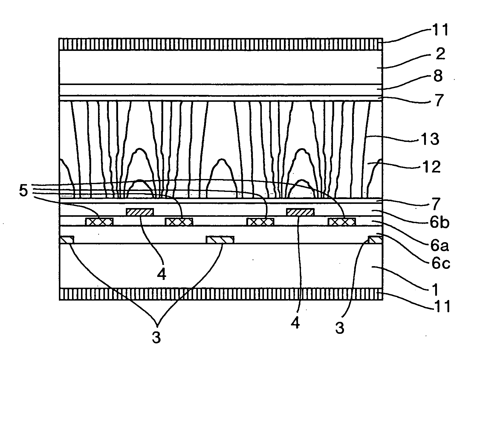
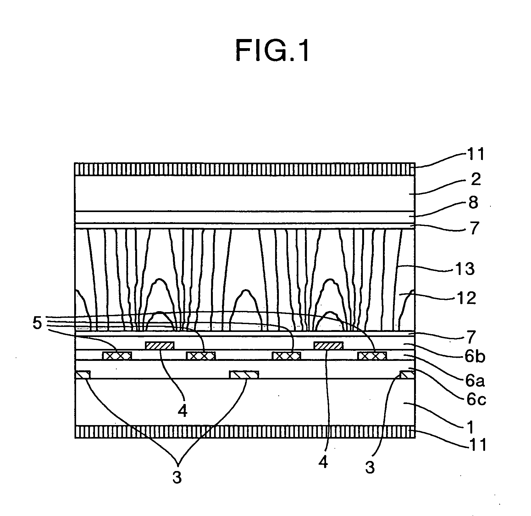
[0110] In Embodiment 2, the ratio of the potentials provided to the common electrode 3, the first pixel electrode 4, and the second pixel electrode 5 is different from that in Embodiment 1. This is because the area through which light is transmitted changes to vary the average of EZ / EX in the area through which light is transmitted. This will be described with reference to FIG. 1. As is apparent from the equipotential lines 13 in FIG. 1, the area on the common electrode 3 and the first pixel electrode 4 has a larger EZ / EX than the area between the common electrode 3 and the first pixel electrode 4. Thus, if the common electrode 3 and the first pixel electrode 4 ...

embodiment 3

[Embodiment 3]

[0112] Embodiment 3 of the liquid crystal display apparatus according to the present invention is the same as the liquid crystal display apparatus of Embodiment 1 except that the second pixel electrode 5 overlaps the common electrode 3 and is made of chromium molybdenum like the common electrode 3 and the first pixel electrode 4, as shown in FIG. 10.

[0113] In this embodiment, even if the second pixel electrode 5 is not transparent, the aperture ratio does not decrease. Accordingly, the material of the electrodes can be selected more flexibly.

[0114] Similar effects are also obtained if the second pixel electrode 5 overlaps the first pixel electrode 4.


PUM

PropertyMeasurementUnit
thicknessaaaaaaaaaa
thicknessaaaaaaaaaa
widthaaaaaaaaaa

Abstract

A liquid crystal display apparatus includes a substrate and a second substrate with a liquid crystal layer sandwiched therebetween. A plurality of pixels are sandwiched between the two substrates and form a display section, each of the pixels is provided with first and second pixel electrodes both corresponding to the pixel, and a common electrode corresponding to the first and second pixel electrodes.

Description

CROSS REFERENCE TO RELATED APPLICATION [0001] This application is a continuation of U.S. application Ser. No. 09 / 938,619, filed Aug. 27, 2001, now U.S. Pat. No. 6,859,194, the contents of which are incorporated herein by reference.BACKGROUND OF THE INVENTION [0002] The present invention relates to a liquid crystal display apparatus having a new configuration. [0003] Conventional liquid crystal display apparatuses employ a display mode represented by a Twisted Nematic (TN) display mode and in which electric fields are applied substantially perpendicularly to a substrate surface (these electric fields are hereinafter referred to as “vertical fields”). The TN display mode, however, has the disadvantage of using a small angle of visibility. [0004] On the other hand, an In-Plane Switching (IPS) display mode has been proposed in JP-B-63-21907, U.S. Pat. No. 4,345,249, WO No. 91 / 10,936, and JP-A-6-160878 and etc. specifications. [0005] In this IPS display mode, an electrode for driving liq...

Claims


Application Information

Patent Timeline
Patent Type & Authority Applications(United States)
IPC IPC(8): G02F1/133G02F1/1343
CPCG02F1/134363G02F1/1343
Inventor AOYAMA, TETSUYAKOMURA, SHINICHIUTSUMI, YUKA
Owner PANASONIC LIQUID CRYSTAL DISPLAY CO LTD
Why Eureka
Try Eureka