Surveillance camera and surveillance camera system

a surveillance camera and camera system technology, applied in the field of surveillance cameras, can solve the problems of inability to identify the room, inability to receive gps signals, and inability to identify the installation position using gps signals, and achieve the effect of easy inclusion of theft prevention functions

Inactive Publication Date: 2005-06-30
FUNAI ELECTRIC CO LTD
View PDF5 Cites 44 Cited by
  • Summary
  • Abstract
  • Description
  • Claims
  • Application Information

AI Technical Summary

Benefits of technology

[0019] With this surveillance camera, the GPS signal for transmitting current position data is used to enable a theft signal to be transmitted to the surveillance apparatus as a theft prevention alarm. Therefore, a theft prevention function can be easily included.

Problems solved by technology

When the surveillance cameras need to be installed indoors, however, a GPS signal cannot be received.
Therefore, the installation position cannot be identified using a GPS signal.
For instance, when the surveillance camera is moved from one indoor room to another it is impossible to identify the room in which the surveillance camera is installed, since a GPS signal cannot be received by the surveillance camera.
Thus, it is difficult to accurately identify the installation position of the surveillance camera.
Also, when it is necessary to distinguish between rooms on different floors, it is even more difficult to determine the installation position.

Method used


Image

  • Surveillance camera and surveillance camera system
  • Surveillance camera and surveillance camera system
  • Surveillance camera and surveillance camera system

Examples


Embodiment Construction

[0036] Selected embodiments of the present invention will now be explained with reference to the drawings. It will be apparent to those skilled in the art from this disclosure that the following descriptions of the embodiments of the present invention are provided for illustration only and not for the purpose of limiting the invention as defined by the appended claims and their equivalents.

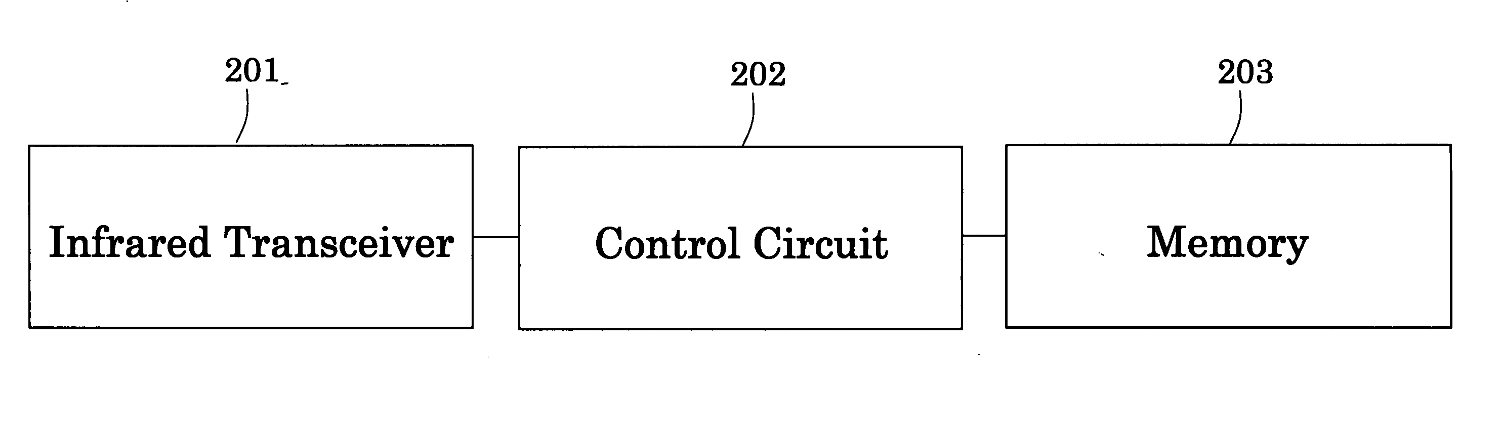
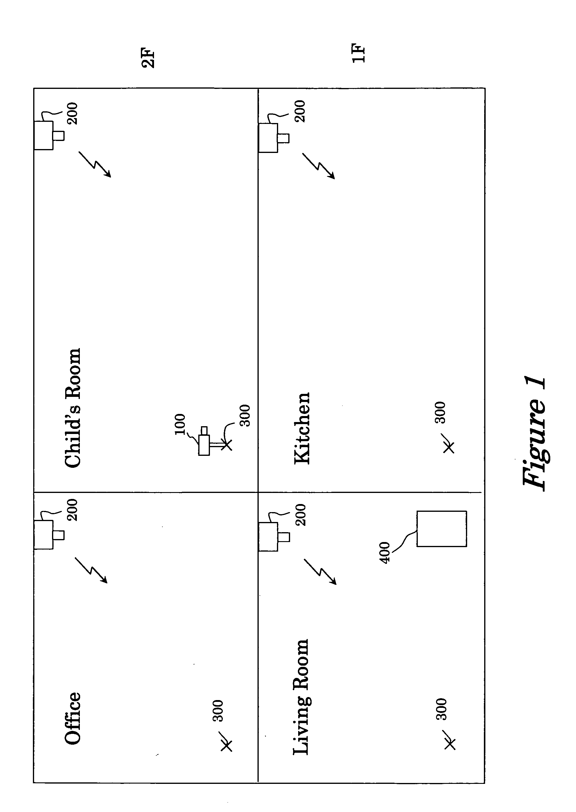
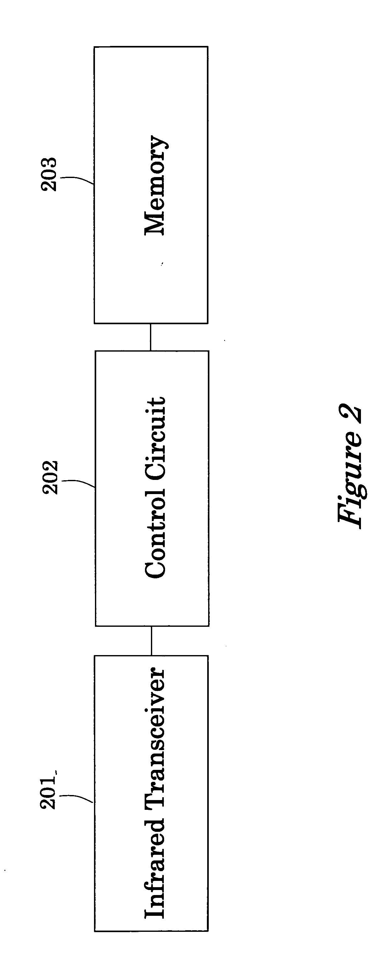
[0037]FIG. 1 is a schematic structural diagram of the surveillance camera system according to an embodiment of the present invention. The surveillance camera system has a plurality of infrared beacons 200, a surveillance camera 100 that obtains position data from the infrared beacon 200 and captures images to create picture signals, and a surveillance apparatus 400 for receiving picture signals combined with position data from the surveillance camera 100.

[0038] As shown in FIG. 1, one infrared beacon 200 is installed in each room, such as a child's room, the kitchen, office, and the living room....


PUM


Abstract

A surveillance camera that transmits image data to a remote surveillance apparatus has an image capturing portion, an infrared receiver for receiving infrared signals from an infrared beacon disposed in each room, a GPS receiver for receiving GPS signals from a satellite positioning system, a picture combining portion for combining current position data contained in the infrared signal or the GPS signal with pictures obtained by the image capturing portion, a transmitter for transmitting combined signal of the current position data and image data to the surveillance apparatus, a memory for storing the optimal orientation data for the surveillance camera placed in a predetermined position, and a light-emitting unit for emitting light when the surveillance camera has the optimal orientation. The surveillance camera identifies the optimal orientation when the installation position of the surveillance camera is moved between different rooms.

Description

BACKGROUND OF THE INVENTION [0001] 1. Field of the Invention [0002] The present invention relates to a surveillance camera. More particularly, the present invention relates to a surveillance camera for transmitting image data to a remote surveillance apparatus. Also, the present invention relates to a surveillance camera system having such surveillance camera and such remote surveillance apparatus, in which image data taken with the surveillance camera is transmitted to the remote surveillance apparatus. [0003] 2. Background Information [0004] Japanese Laid-Open Patent Application No. 10-285585 discloses a surveillance camera that is to be disposed outdoors, wherein the installation position of the surveillance camera is identified by using a GPS (Global Positioning System) signal transmitted from a satellite, and the installation position is output as position data together with pictures. When pictures and position data are received by a remote surveillance camera apparatus, the pi...

Claims


Application Information

Patent Timeline
Patent Type & Authority Applications(United States)
IPC IPC(8): G08B13/18H04N7/18G08B25/10
CPCH04N7/20H04N7/181
Inventor AKAMATSU, KENJI
Owner FUNAI ELECTRIC CO LTD
Why Eureka
Try Eureka