Microscope device
- Summary
- Abstract
- Description
- Claims
- Application Information
AI Technical Summary
Benefits of technology
Problems solved by technology
Method used
Image
Examples
first embodiment
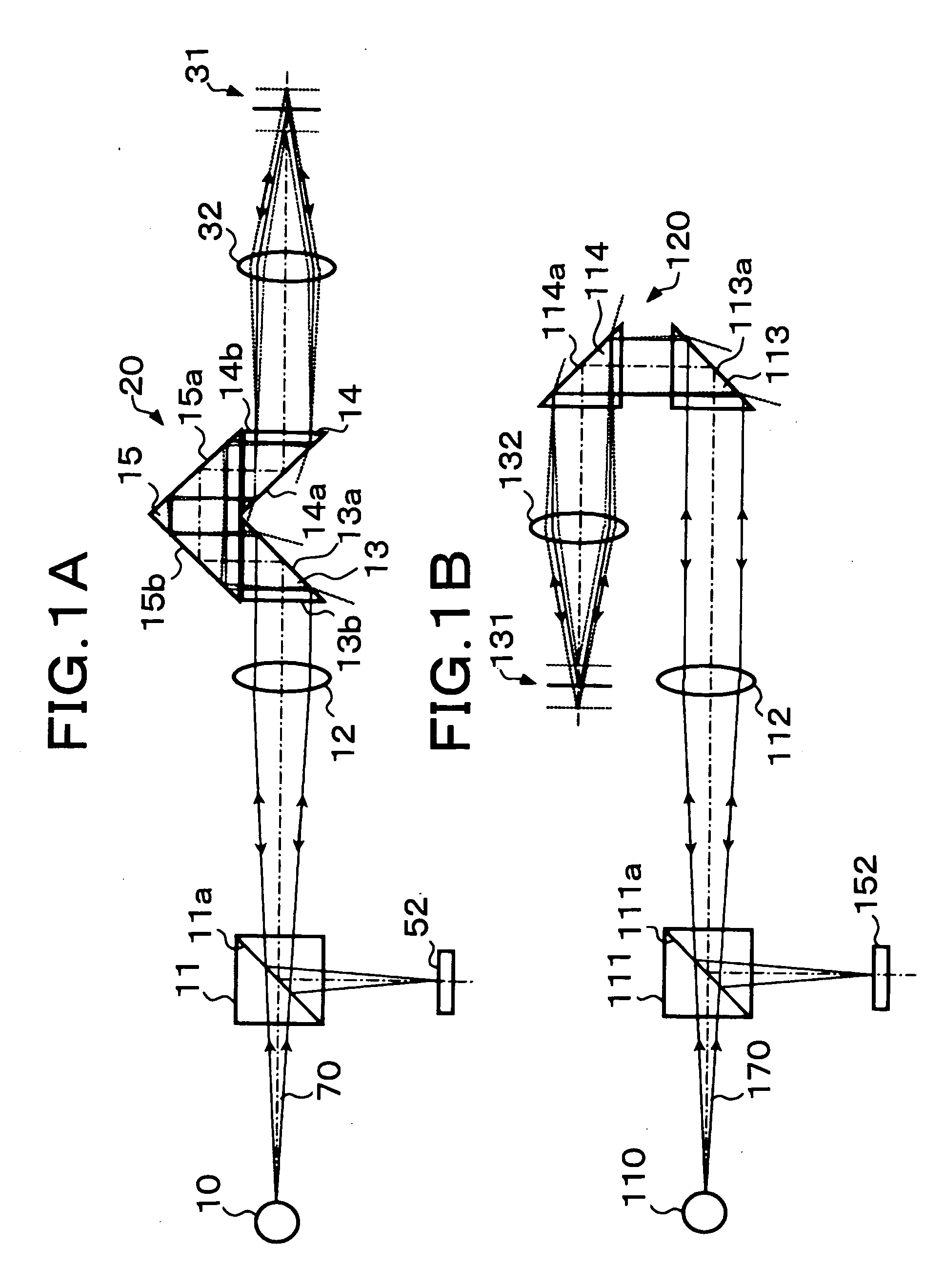
[0043]FIG. 1A shows the configuration of the
[0044] A light beam 70 emitted from a point light source 10 travels through a half prism 11, a collimator lens 12, a parallel beam selection means 20 and an objective lens 32 to be converged at a desired position on an object 31. The light beam emitted from the point light source 10 is in a divergent state but it is formed into a parallel beam along an optical axis by the collimator lens 12, so that substantially the entire light beam passes through the parallel beam selection means 20. When the parallel light beam that has passed through the parallel beam selection means 20 is converged on the above-mentioned desired position by the objective lens 32, the desired position coincides with the focal point of the objective lens 32.
[0045] If the entire reflected light from the above-mentioned desired position (convergence position) on the object 31 is specularly reflected light, it is supposed to be converted into a parallel light beam by the...
second embodiment
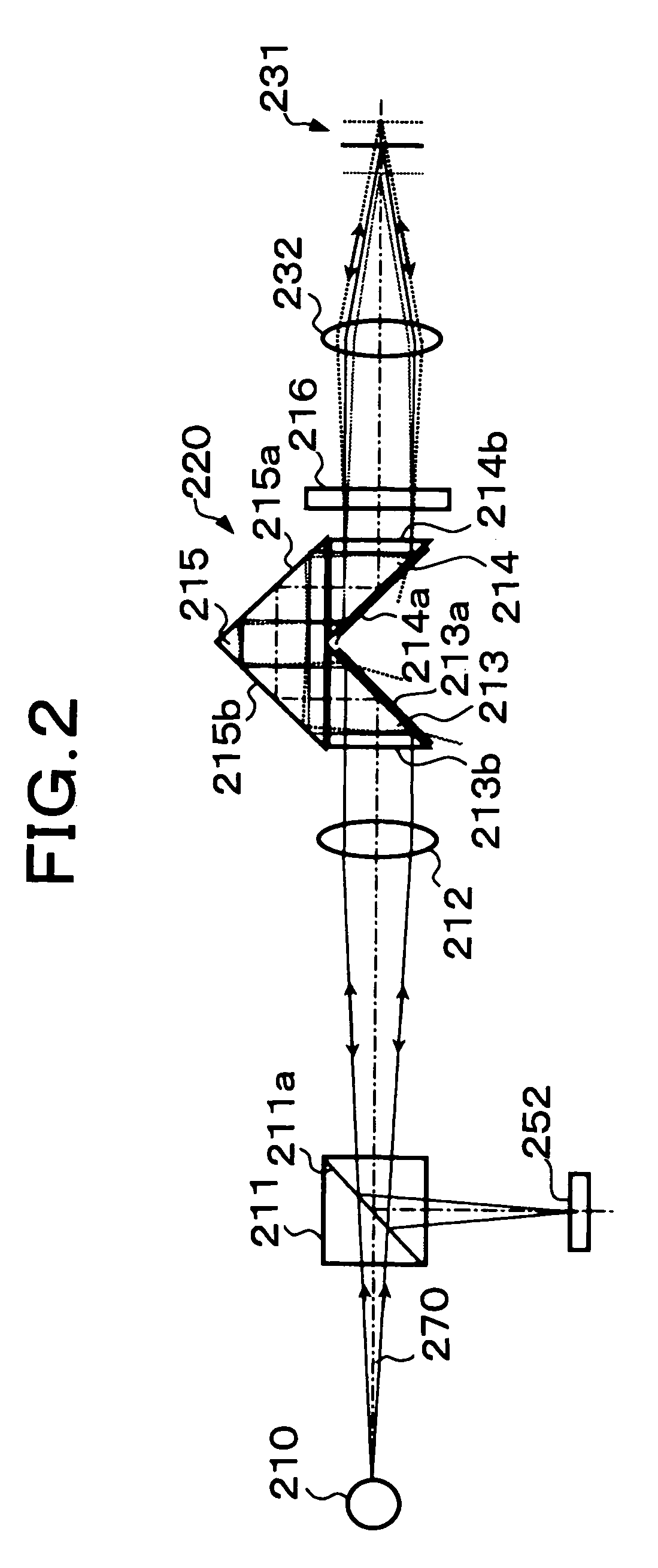
[0052] In the second embodiment shown in FIG. 2, a polarization beam splitter 211 is provided in place of the above-described half prism 11, and a {fraction (1 / 4 )} wavelength plate 216 is provided between a parallel beam selection means 220 and an objective lens 232.
[0053] In the second embodiment, illumination light transmits through the polarization beam splitter 211 to be converted into one linear polarization (s-polarization), and return light is converted into another linear polarization (p-polarization) by transmitting through the ¼ wavelength plate 216 two times. Therefore, generally the entire light beam returned to the polarization beam splitter 211 is reflected by a polarization reflecting surface 211a. In this way, a fine light spot carrying object information can be obtained with efficiency.
[0054] Each of oblique surfaces 213a and 214a of two critical-angle prisms 213 and 214 in the parallel beam selection means 220 is coated with an optical thin film for increasing th...
third embodiment
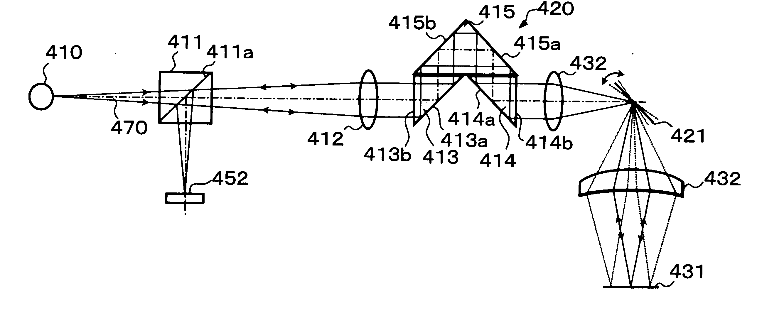
[0057] The third embodiment shown in FIGS. 3A and 3B is arranged so that an object surface (convergence surface) 331 or 431 is one-dimensionally or two-dimensionally scanned with a light beam emitted from a parallel beam selection means 320 or 420. That is, one-dimensional or two-dimensional scanning with the light beam is performed by means of an optical scanner 321 or 421, e.g., a galvanometer mirror or a polygon mirror placed on the light source 310 or 410 side of an objective lens 332 or 432. It is possible to one-dimensionally or two-dimensionally obtain information on the object surface 331 or 431 by scanning the object surface with the illumination light beam in this manner.
[0058] In the arrangement shown in FIG. 3A, the illumination light beam is emitted to the optical scanner 321 in a state of being formed as a parallel light beam. In the arrangement shown in FIG. 3B, the illumination light beam is emitted to the optical scanner 421 while being converged from the parallel b...
PUM
 Abstract
Description
Claims
Application Information
 - R&D
- Intellectual Property
- Life Sciences
- Materials
- Tech Scout
- Unparalleled Data Quality
- Higher Quality Content
- 60% Fewer Hallucinations
Browse by: Latest US Patents, China's latest patents, Technical Efficacy Thesaurus, Application Domain, Technology Topic, Popular Technical Reports.
© 2025 PatSnap. All rights reserved.Legal|Privacy policy|Modern Slavery Act Transparency Statement|Sitemap|About US| Contact US: help@patsnap.com


