
Three quarter spatially variant apodization

a spatial variant and image processing technology, applied in the field of image processing, can solve the problems of requiring a significant amount of post-processing data, preventing technology from being fully exploited, and consuming a lot of resources, so as to achieve less waste of throughput and memory, and less zero filling

Active Publication Date: 2011-10-20
RAYTHEON CO
View PDF3 Cites 3 Cited by
  • Summary
  • Abstract
  • Description
  • Claims
  • Application Information

AI Technical Summary

Benefits of technology

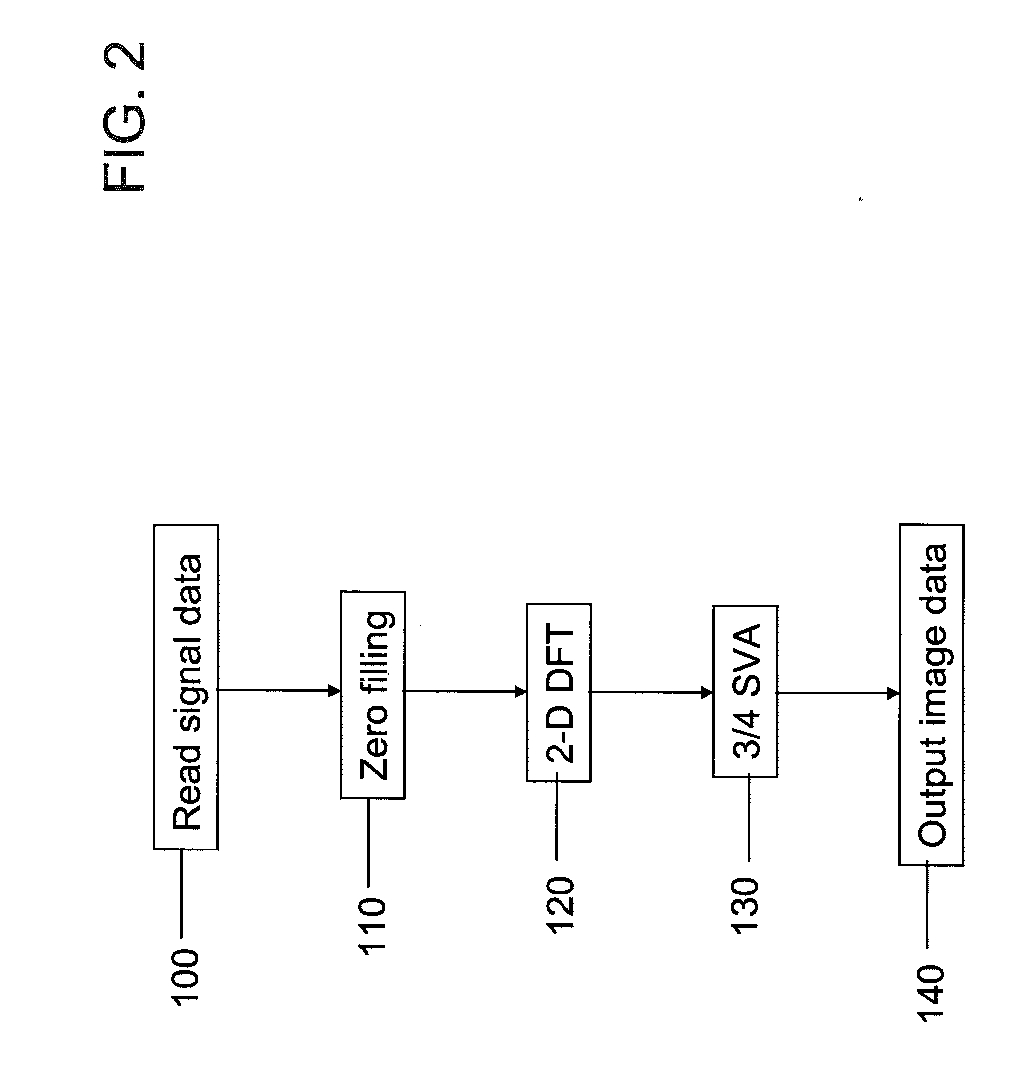
[0014]To address the above problems, embodiments using a new spatially variant apodization (SVA) algorithm suitable for use in image processing and image enhancement are presented. The technique works with any rectangular coherent aperture in the spatial frequency domain. The SVA algorithm uses a 3 / 4 filled aperture prior to two-dimensional DFT to form the image. The 3 / 4 SVA algorithm (3 / 4 SVA) described here is an attempt to supply an SVA algorithm that works from a 3 / 4 aperture filling ratio, which is less wasteful of throughput and memory in ATR applications, and produces an image where the pixel spacing is about 85% of the resolution, which is comparable to the oversampling used with Taylor weighting (a traditional weighting function for sidelobe suppression, but is not spatially variant). This is because the 3 / 4 SVA does significantly less zero filling than with 1 / 2, 1 / 3, or higher (integer) ratios.
[0015]This algorithm can be used, for example, to improve contrast and resolution on Synthetic Aperture Radar (SAR) imagery, with a lower degree of oversampling than other algorithms require. That is, the algorithm attempts to produce the same or better image quality as with higher oversampling, only using coarser pixel spacing. This can translate into more efficient use of radar displays and processor memory. Additional efficiencies of memory and computing power may be realized when Automatic Target Recognition (ATR) algorithms operate on this imagery, because processing time increases as at least the square (and often the cube) of the number of pixels representing a target, so better contrast and fewer pixels greatly reduces this computational overhead.
[0016]Embodiments of this invention use convolution kernels at two different spacings, which are better tuned to the local phase relationships of mainlobe and sidelobes with a 3 / 4 filled aperture. There are two levels of phase testing, at two different spacings (one using 3×3 kernels spaced four samples apart and one using 3×3 kernels spaced two samples apart). The embodiments also suppress sidelobes without sacrificing resolution, at an aperture-filling ratio of 3 / 4, rather than 1 / 2, as is usually used. Since the aperture-filling ratio is linearly proportional to the ratio of pixel spacing to resolution, this allows for less highly oversampled imagery. For example, at an aperture-filling ratio of 1 / 2, the pixel spacing is about 56% of resolution, whereas at an aperture filling of 3 / 4, the pixel spacing is about 85% of resolution. This coarser spacing allows for more efficient use of system memory and for improved system throughput.

Problems solved by technology

Image processing of received antenna data (such as from a synthetic aperture radar) can be very computationally intensive.
Converting the antenna data, for example, often involves Fourier transforms of the data, which introduces sidelobes (that interfere with the interpreting of the mainlobe, that is, the desired signal).
However, the significant processing requirements (for example, normalizing the image to correct for things like curvature and Doppler effect) have kept SAR technology from being fully exploited until the capabilities of modern computing systems.
This requires a significant amount of post-processing of the data, typically done with a digital computer.
Processing the image data can involve Fourier transforms, such as a discrete Fourier transform (DFT) or fast Fourier transform (FFT), of the data, but this can also introduce sidelobes (noise) to the mainlobe (data of interest).
As can be seen in FIG. 5, there is a main beam of interest (that provides the desired signal data), but it creates noise in the form of sidelobes.
Spatially invariant reduction of sidelobes (e.g., Taylor weighting) has the drawback of widening the mainlobe, which reduces resolution.
The 1 / 2 ratio is most commonly used, however it results in nearly 2:1 oversampling of the image, and is wasteful of pixel real-estate, automatic target recognition (ATR) or other image processing, and memory loading.

Method used


Image

  • Three quarter spatially variant apodization
  • Three quarter spatially variant apodization
  • Three quarter spatially variant apodization

Examples


Embodiment Construction

[0038]Exemplary embodiments of the present invention will now be described in more detail with reference to the accompanying drawings.

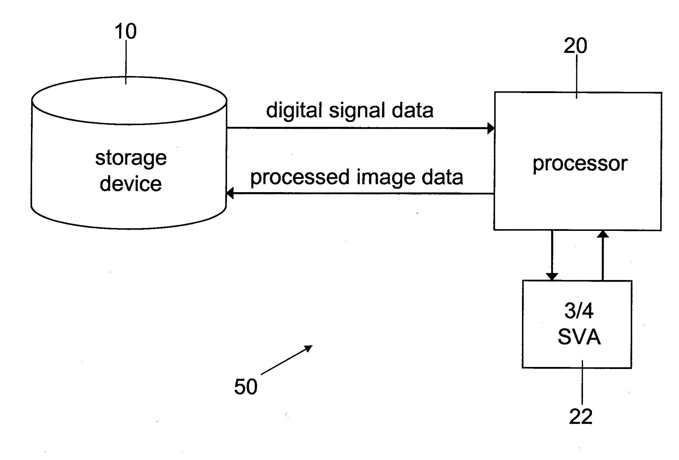
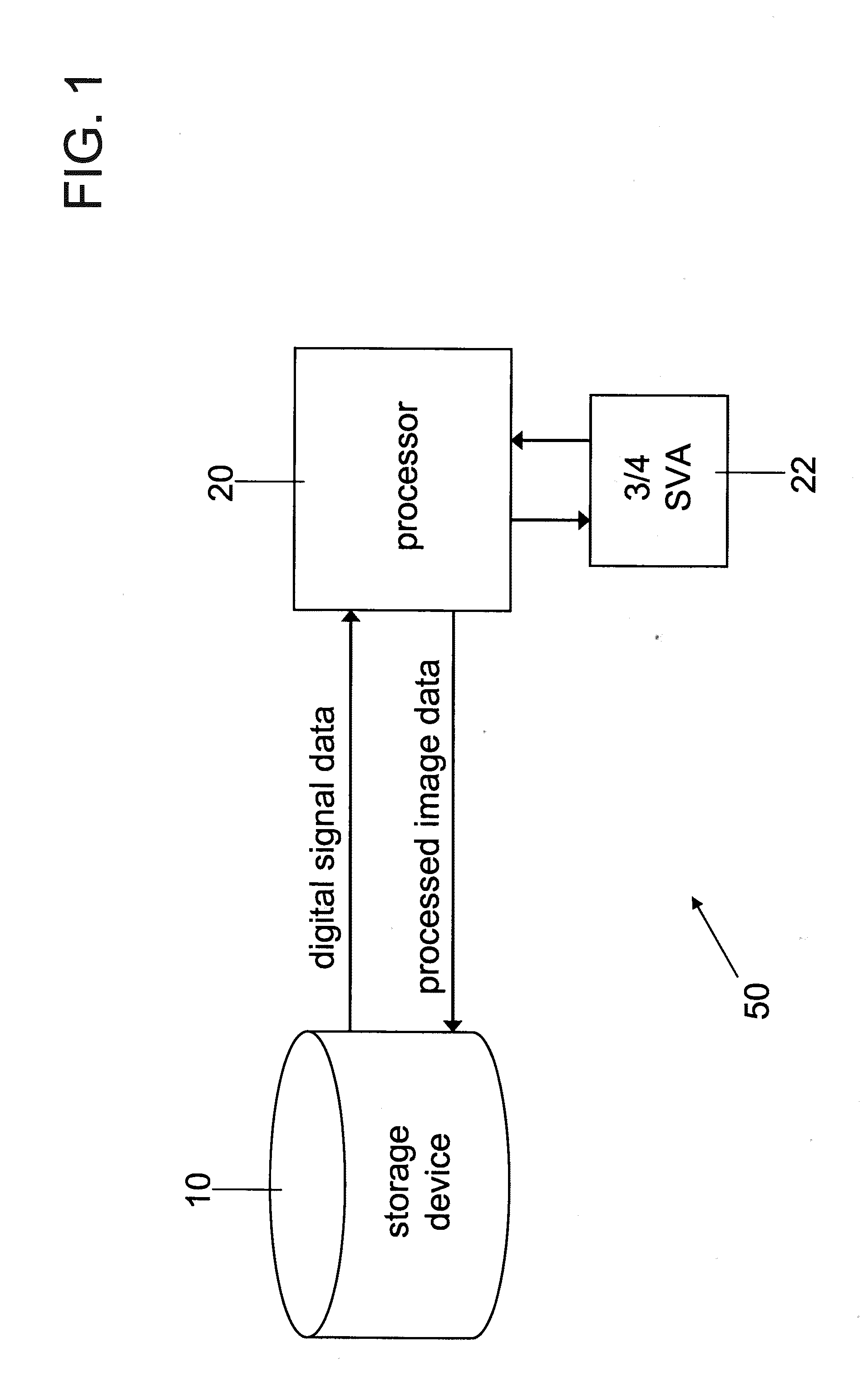
[0039]FIG. 1 is an image processing system according to an exemplary embodiment of the present invention.

[0040]Referring now to FIG. 1, an image processing system 50 using 3 / 4 SVA is shown. The image processing system 50 includes a storage device 10 adapted to stored sensed signal data and processed image data, a processor 20, and a 3 / 4 SVA component 22 adapted to run on the processor 20 and do 3 / 4 SVA processing to the image data.

[0041]In more detail, sensed digital signal data—for example, from a synthetic aperture radar (SAR)—is stored on storage device 10. Assume, for simplicity, that the digital signal data represents image signal data in the spatial frequency domain (the technique should work with any rectangular coherent aperture in the spatial frequency domain). The digital signal data is stored in a two-dimensional matrix, each two-variable e...


PUM


Abstract

A new spatially variant apodization (SVA) algorithm that uses a 3 / 4 filled aperture prior to two dimensional discrete Fourier transform (2-D DFT) to form the image. The algorithm can be used, for example, to improve contrast and resolution on synthetic aperture radar (SAR) imagery, with a lower degree of oversampling (and thus, fewer pixels) than other algorithms require. This can translate into more efficient use of radar displays and processor memory. Additional efficiencies of memory and computing power may be realized when Automatic Target Recognition (ATR) algorithms operate on this imagery. Embodiments of this invention use convolution kernels at two different spacings, which are better tuned to the local phase relationships of mainlobe and sidelobes with a 3 / 4 filled aperture. As such, these embodiments suppress sidelobes without sacrificing resolution, at an aperture-filling ratio of 3 / 4, rather than 1 / 2, as is usually used.

Description

BACKGROUND OF THE INVENTION[0001]1. Technical Field[0002]The disclosed technology relates to image processing. More specifically, the disclosed technology relates to sidelobe suppression and pixel reduction in image processing.[0003]2. Brief Description of the Related Art[0004]Image processing of received antenna data (such as from a synthetic aperture radar) can be very computationally intensive. Some of this computation is directed to forming the image (converting analog antenna receiver data into digital image data, or pixels) while some is directed to interpreting the image. Converting the antenna data, for example, often involves Fourier transforms of the data, which introduces sidelobes (that interfere with the interpreting of the mainlobe, that is, the desired signal). On the other hand, interpreting the image often involves analyzing the pixels, whose analysis can grow as the square (or higher exponentiation) of the number of pixels, as well as the contrast and resolution of...

Claims


Application Information

Patent Timeline
IPC IPC(8): G01S13/90G01S13/00
CPCG01S7/295G01S13/9035G01S7/411G01S13/9004
Inventor PETERSON, TIMOTHY T.
Owner RAYTHEON CO
Learn More