Fluorescence imaging lighting device, imaging system and imaging method based on speckle principle
A fluorescence imaging and lighting device technology, which is applied in the fields of analysis using fluorescence emission, medical science, diagnosis using tomography, etc. Effect
- Summary
- Abstract
- Description
- Claims
- Application Information
AI Technical Summary
Problems solved by technology
Method used
Image
Examples
Embodiment 1
[0095] Example 1 In situ optogenetics-monochromatic fluorescence imaging system
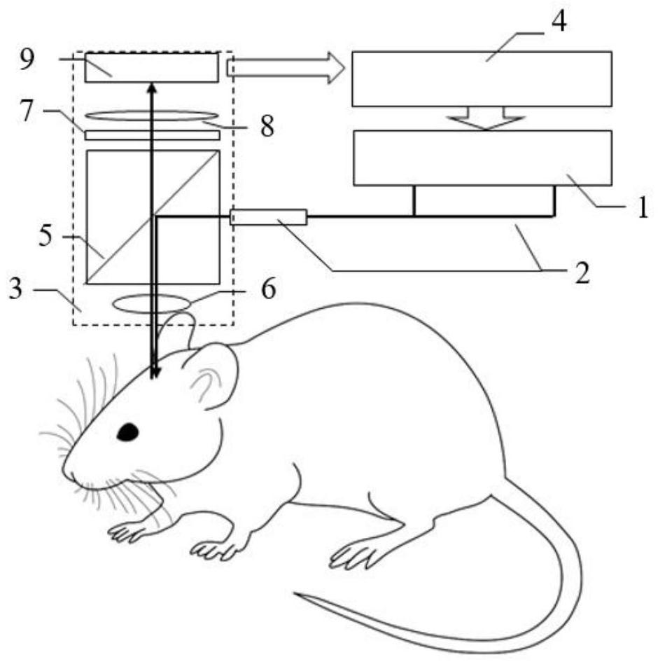
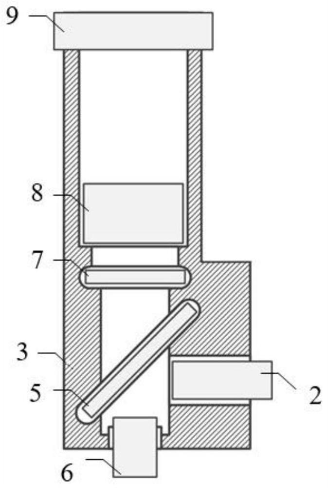
[0096] Taking the application of in situ optogenetics-monochromatic fluorescence imaging as an example, an improved miniature fluorescence imaging system provided by the present invention is described in detail below, such as figure 1 , figure 2 As shown, including fluorescent imaging lighting device, mirror body 3 and acquisition control unit 4
[0097] The mirror body 3 is fixed on the target to be imaged, such as the head, and the mirror body 3 is a miniature fluorescence microscope, including a dichroic mirror 5, an objective lens 6, a fluorescence filter 7, an imaging lens 8 and an image acquisition device 9.
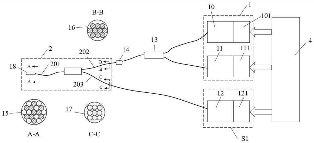
[0098] The fluorescent imaging illumination device includes: a mixed excitation light generation unit 1 , an optogenetic stimulation light generation unit S1 , and a coupling fiber bundle 2 .
[0099] The detailed structure and connection method of the mixed excitation light genera...
Embodiment 2
[0107] Example 2 In situ optogenetics-monochromatic fluorescence imaging system
[0108] The following is another implementation of in situ optogenetics-monochromatic fluorescence imaging application, in order to illustrate an improved miniature fluorescence imaging system provided by the present invention, most of its structure is the same as that of the system in Example 1, the same The details will not be repeated here, and only the differences from Embodiment 1 will be described here.
[0109] system such as figure 1 , figure 2 As shown, this part is all the same as Embodiment 1, the difference is:
[0110] The detailed structure and connection method of the mixed excitation light generating unit 1 and the coupling fiber bundle 2 of the fluorescence imaging illumination device are as follows: Figure 4 shown.
[0111] The mixed excitation light generating unit 1 includes: a laser 10 and its driving module 101, the laser 10 emits 450nm fluorescence excitation light, an...
Embodiment 3
[0116] Example 3 In situ optogenetics-monochromatic fluorescence imaging method
[0117] An improved micro-fluorescence imaging method provided by the present invention will be described in detail below in conjunction with the systems of Examples 1 and 2.
[0118] Acquisition control unit 4 should be able to communicate with upper computer (computer), by the TTL pulse of software editing fixed frequency and duty cycle by acquisition control unit 4 output, a kind of timing signal that acquisition control unit 4 sends is as follows: Figure 5 shown. Set laser 12, laser 10 and LED11 to turn on when rising edge and keep turning on at high level, turn off when falling edge and keep turning off when low level, image acquisition device 9 starts to collect an image when rising edge . For simplicity of description, it is assumed that the 633nm stimulating light is always turned on during the experiment. In actual use, TTL pulses should be edited to control the on-off time and intensi...
PUM
| Property | Measurement | Unit |
|---|---|---|
| Diameter | aaaaa | aaaaa |
| Diameter | aaaaa | aaaaa |
| Diameter | aaaaa | aaaaa |
Abstract
Description
Claims
Application Information
 - R&D
- Intellectual Property
- Life Sciences
- Materials
- Tech Scout
- Unparalleled Data Quality
- Higher Quality Content
- 60% Fewer Hallucinations
Browse by: Latest US Patents, China's latest patents, Technical Efficacy Thesaurus, Application Domain, Technology Topic, Popular Technical Reports.
© 2025 PatSnap. All rights reserved.Legal|Privacy policy|Modern Slavery Act Transparency Statement|Sitemap|About US| Contact US: help@patsnap.com


