X-ray generating device

a generation device and generating device technology, applied in the direction of x-ray tubes, x-ray tube details, nuclear engineering, etc., can solve the problems of difficult to converge the radiated electron beam onto a single point on the x-ray target or achieve a micro focusing, the electrode arrangement around the cathode may take up too large a space, and the focusing electrode or the magnetic pole is required. , to achieve the effect of economically compact and compact devi

Inactive Publication Date: 2005-06-30
SHOWA OPTRONICS
View PDF3 Cites 8 Cited by
  • Summary
  • Abstract
  • Description
  • Claims
  • Application Information

AI Technical Summary

Benefits of technology

[0015] The present invention can thus provide an X-ray generating device which is free from the problems of the prior art, and capable of producing a properly micro focused electron beam of a desired intensity. Furthermore, the X-ray generating device according to the present invention can be manufactured economically and designed as a highly compact device.

Problems solved by technology

The equipotential lines y are therefore somewhat disturbed so that it is difficult to converge the radiated electron beam onto a single point on the X-ray target or to achieve a micro focusing.
However, these prior proposals have some problems that are desired to be eliminated.
In the first instance, a desired micro focusing may be achieved, but a highly complex and unacceptably large focusing electrode or magnetic pole is required.
Therefore, the electrode arrangement around the cathode may take up too large a space for some applications, and is unacceptably expensive to manufacture.
In the second instance, an electron beam of a desired intensity may not be obtained, and it means an X-ray beam of a desired intensity may not be obtained.
Also, a slightly spreading of electrons around the point of micro focusing is inevitable, and it means a lack of contrast in the produced X-ray beam.

Method used


Image

  • X-ray generating device
  • X-ray generating device
  • X-ray generating device

Examples


Embodiment Construction

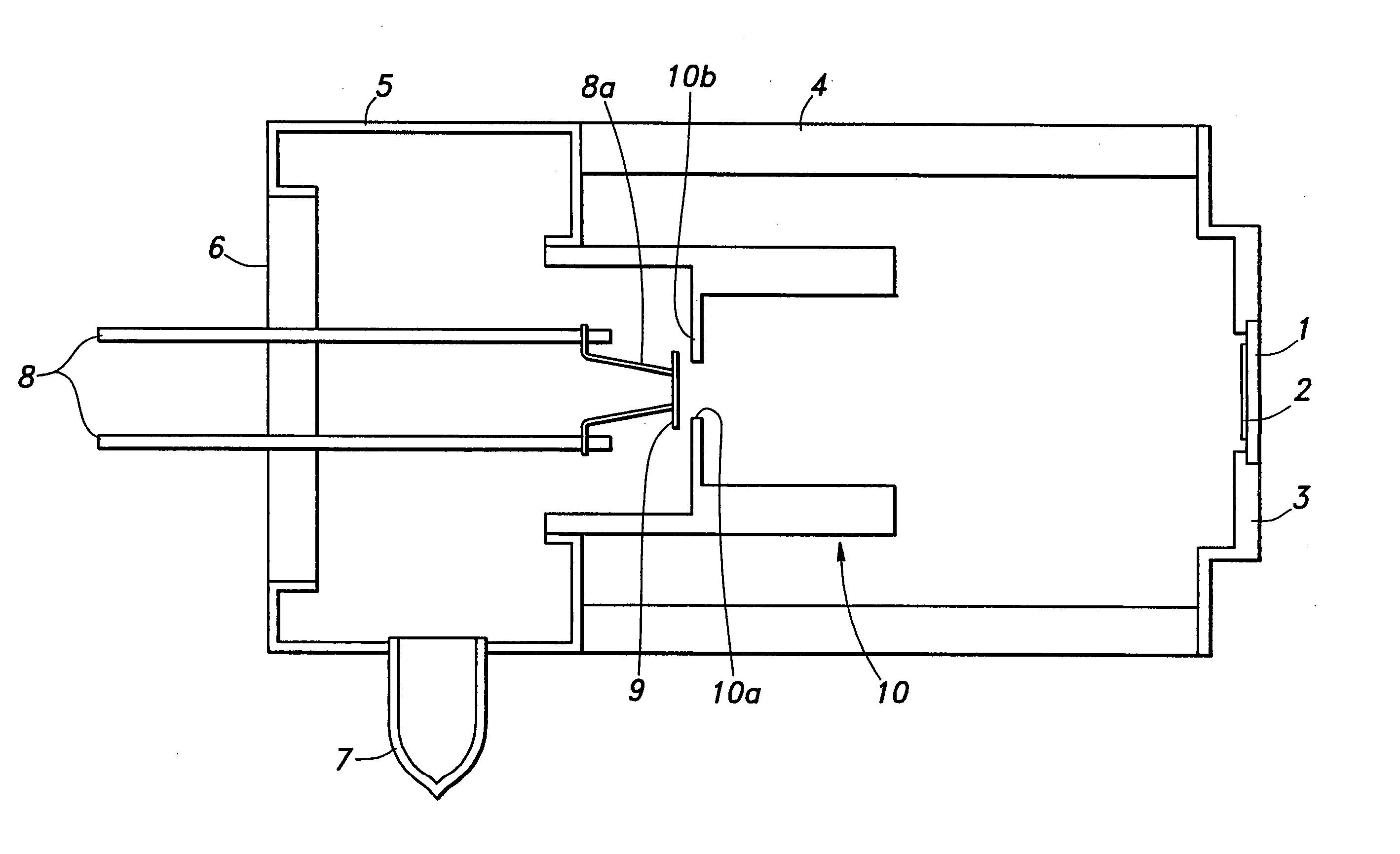
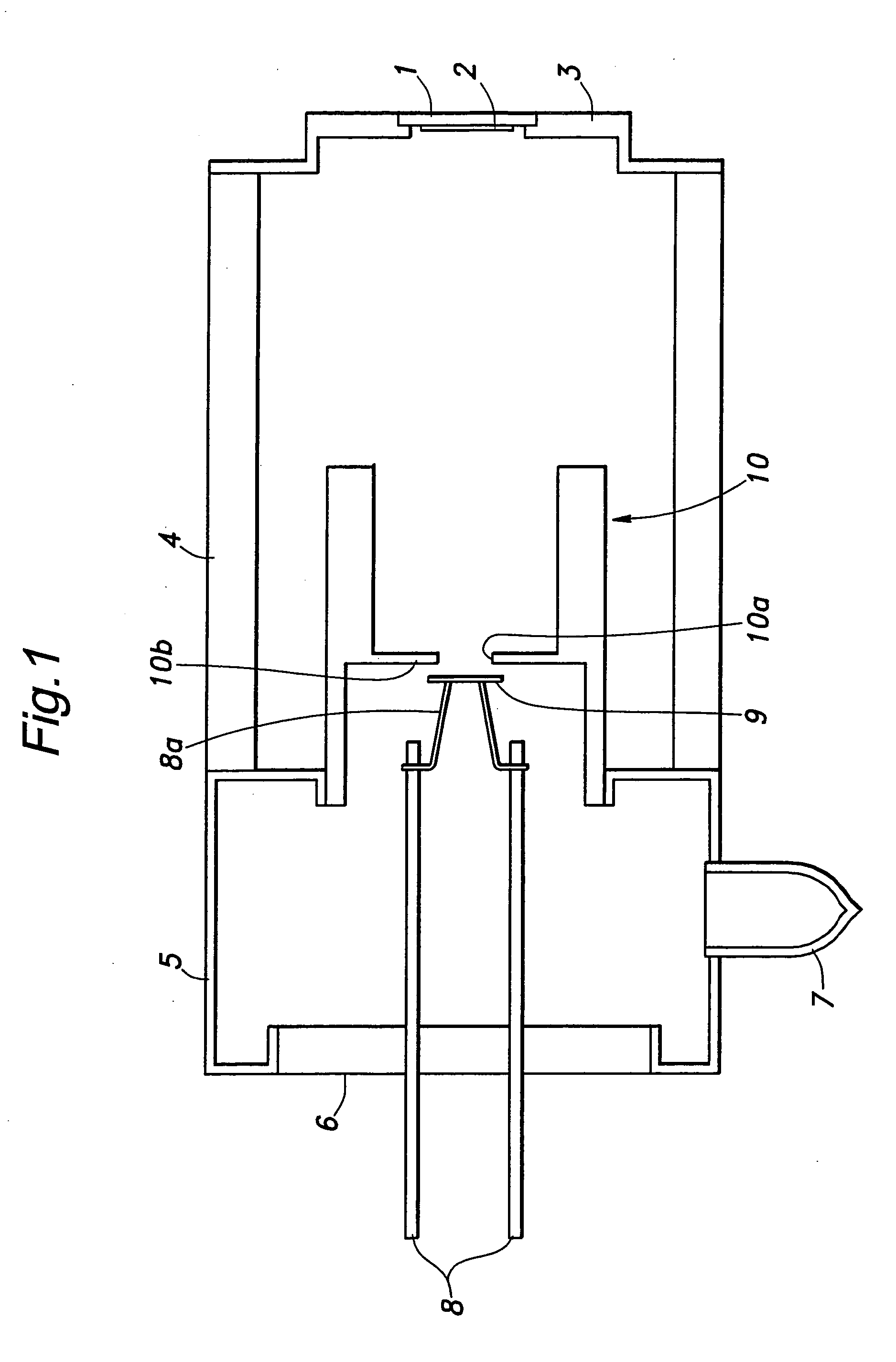
[0021]FIG. 1 shows a sectional view of an X-ray generating device embodying the present invention which comprise a housing defining an evacuated envelope. The anode end of the housing comprises a cylindrical section 4 and an end plate 3 both made of insulating material such as ceramics. The end plate 3 is provided with an X-ray window 1, an X-ray target 2 placed thereon and an electrode for applying a high voltage to the X-ray target 2. The X-ray target 2 forms the anode which emits X-ray radiation when impacted by an electron beam.

[0022] The cathode end of the housing similarly comprises a cylindrical section 5 and an end plate 6. The end plate 6 is provided with a pair of lead terminals 8 which are connected to an external heater power source (not shown in the drawings). A disk-shaped planar cathode 9 is attached to a filament 8a which is in turn connected to the lead terminals 8. The cylindrical section 5 is provided with an evacuation tube 7 which sealed by fusing after the int...


PUM


Abstract

An X-ray generating device comprises a focal electrode (10) placed adjacent to the cathode (9) and provided with a focal aperture (10a) aligning with the cathode. A positive voltage is applied to the focal electrode relative to the cathode so that equipotential lines around the focal aperture may bulge toward the X-ray target (2). Thereby, the part of the electron beam having a large diverging angle is captured by the focal electrode, and only the part of the electron beam having a uniform diverging angle is allowed to pass through the focal aperture so that the electron beam can be favorably micro focused upon the X-ray target and can be given with a high intensity.

Description

TECHNICAL FIELD [0001] The present invention relates to an X-ray generating device typically in the form of an X-ray tube for use in medical, industrial and scientific applications, and in particular to an X-ray generating device in which a micro focused electron beam is converged upon an X-ray target. The present invention is highly suitable, not exclusively, for medical imaging purposes and non-destructive testing of semiconductor devices. BACKGROUND OF THE INVENTION [0002] Known X-ray generating devices of this type include those using a focusing electrode or focusing magnetic pole for converging an electron beam as disclosed in Japanese patent publication No. 2002-358919, and those using a cathode assembly including a filament mounting disk for adjustably mounting a flat ribbon filament or a round wire filament so that the filament extends through an aperture in a focal plane disk, and a uniform focusing field may be achieved as disclosed in U.S. Pat. No. 5,077,777. [0003]FIGS. ...

Claims


Application Information

Patent Timeline
Patent Type & Authority Applications(United States)
IPC IPC(8): G21K5/02H01J35/06H01J35/14H05G1/00
CPCH01J2235/18H01J35/14H01J35/147
Inventor ICHIKAWA, KOZOKASHIWA, SEIJI
Owner SHOWA OPTRONICS
Why Eureka
Try Eureka