
Indoor location identification system

Inactive Publication Date: 2005-06-30
CORNING MOBILEACCESS
View PDF4 Cites 87 Cited by
  • Summary
  • Abstract
  • Description
  • Claims
  • Application Information

AI Technical Summary

Benefits of technology

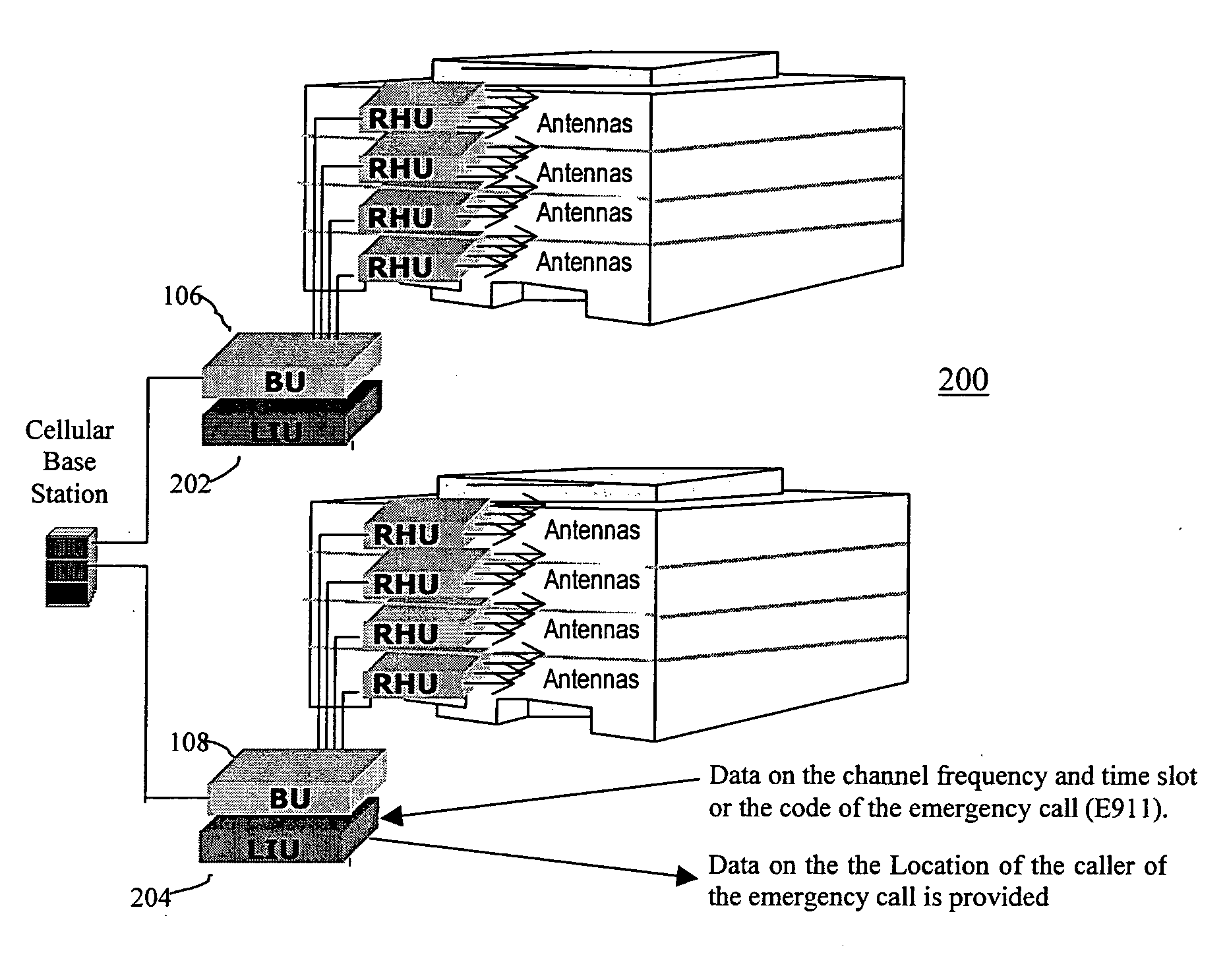
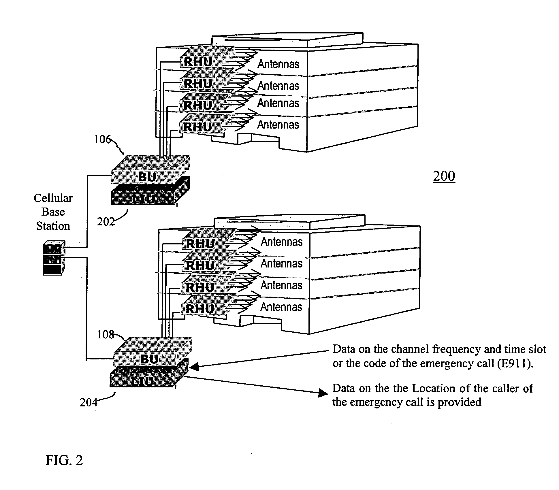
[0011] The present invention is of a system and method for accurate indoor location of a mobile cellular telephone (cellular user) (or simply “indoor location identification”) in case of an emergency in real time. The invention uses an existing DAS-like infrastructure to extract the location of the cellular user from the energy of radio frequency (RF) signals gathered through the antennas of the infrastructure. The DAS-like infrastructure may also serve (but does not have to) as a regular DAS. The RF signals are tapped into and processed by a location identification unit

Problems solved by technology

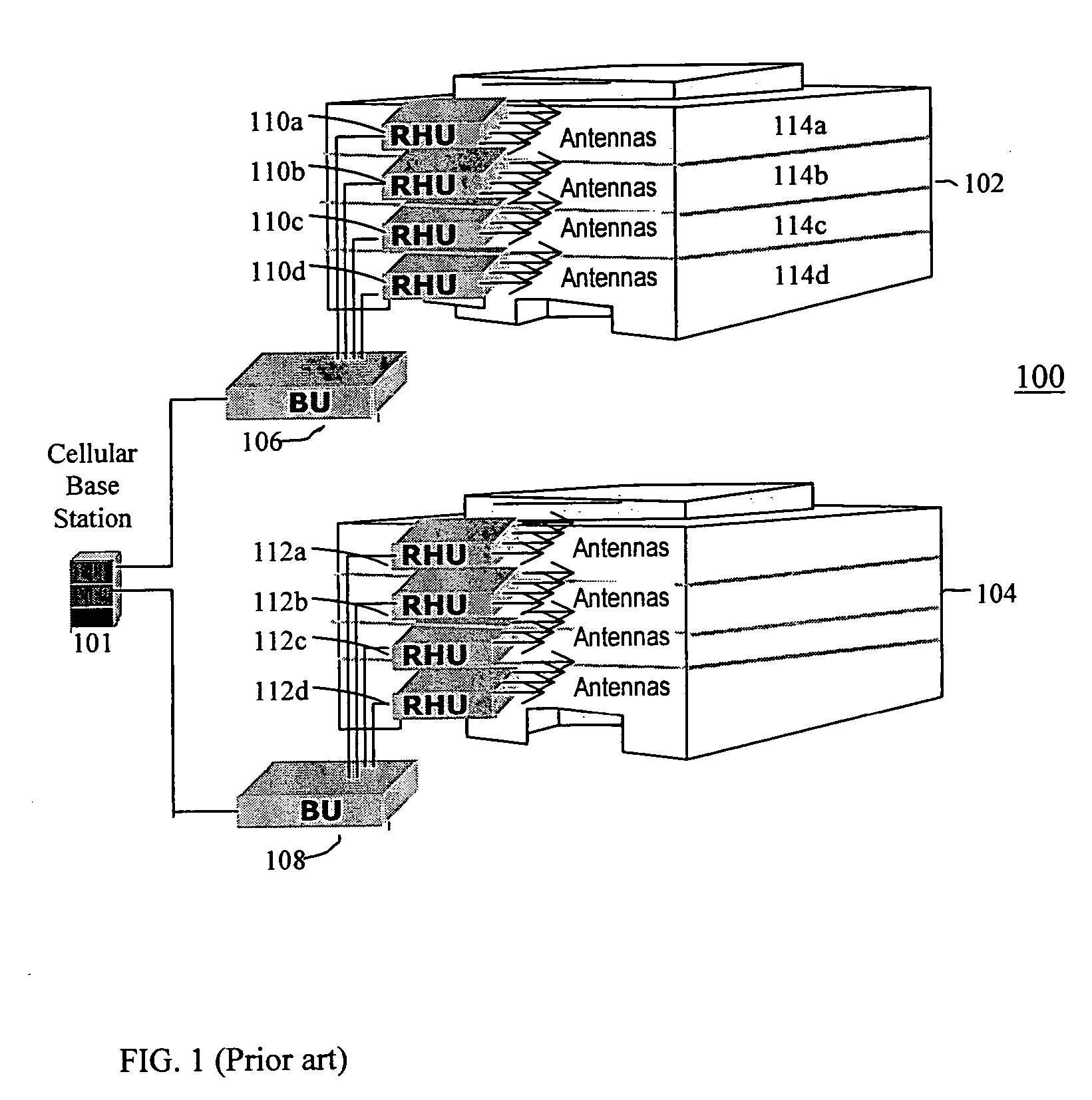
The cellular coverage level in many buildings is not adequate to guarantee a successful call session.
It is obvious that location identification based on any kind of triangulation is not possible in such cases since the subscriber unit is received only by one base station by definition.
Multi-floor buildings pose additional obstacles for indoor location identification, as they require three-dimensional positioning.
Even if the longitude and latitude of an individual cellular telephone in a fifty floor high building were known with great accuracy, that knowledge would be insufficient because an emergency team would have to search every floor.
All these technologies are flawed in terms of their ability to locate indoor cellular callers.
Large steel and concrete buildings, subways and large malls may be difficult or even impossible to cover using traditional wide area location technologies such as AGPS and TDOA.
Low signal levels and signal multipath effects in these environments decrease the location identification accuracy or totally prevent signal acquisition.
None of these technologies can locate a cellular telephone indoors, due to the low signal levels and the fact that these technologies provide in effect only a two-dimensional location identification, where a three-dimensional one is needed.

Method used


Image

  • Indoor location identification system
  • Indoor location identification system
  • Indoor location identification system

Examples


Embodiment Construction

[0021] The present invention is of a system and method for accurate location, in real time, of a mobile cellular telephone in an indoor environment during emergencies (e.g. upon a “911” emergency call). The invention is based advantageously on the fact that a distributed antenna system can be used to monitor the RF signals received in each floor or area of each building covered by the DAS, specifically by the RHU covering that floor or area. The RHU identified with a particular emergency call indicates the location from which the call is made. Such a use of a DAS or DAS-like infrastructure is unknown in prior art, as well as unexpected. The indoor location identification system of the present invention can interface with existing distributed antenna systems, and can, upon request, provide information on the location of an indoor subscriber.

[0022]FIG. 2 shows a preferred embodiment of an indoor location identification system 200 of the present invention. System 200 is shown exemplar...


PUM


Abstract

A system and method or accurate location identification of a mobile cellular telephone in an indoor environment in case of emergency are provided. The system comprises elements of a distributed antenna system (DAS) and at least one location identification unit (LIU) coupled to the DAS and operative to extract the location of the mobile cellular telephone from RF signals obtained from the DAS. The LIU includes a receiver operative to receive the signals, preferably from a base unit (BU) of the DAS, and a processor operative to process the signals. The LIU obtains parameters of the emergency call that define a tuning window from an external system, and, using the tuning window, identifies a remote hub unit (RHU) of the DAS with the highest signal energy at the tuning window as the RHU through which the call was acquired. The location of the mobile cellular telephone is then determined as being in the area covered by this RHU.

Description

CROSS REFERENCE TO RELATED APPLICATIONS [0001] The present invention claims priority from U.S. Provisional Patent Application No. 60 / 499,009 filed 2 Sep., 2003, the content of which is incorporated herein by reference.FIELD AND BACKGROUND OF THE INVENTION [0002] The present invention relates to emergency location services, and in particular to methods and systems for locating individuals inside buildings during emergencies in real time, using cellular technology. [0003] It is expected that within 3-5 years, 50% of cellular calls will be conducted inside buildings. The cellular coverage level in many buildings is not adequate to guarantee a successful call session. Reception of cellular signals in buildings is disturbed because: [0004] 1) Building obstructions (exterior and interior walls) attenuate the signal below the level required for maintaining a link. [0005] 2) In high floors (usually above the clutter), a mobile cellular telephone is exposed to multiple base station signals t...

Claims


Application Information

Patent Timeline
IPC IPC(8): H04W4/90H04W64/00
CPCH04W4/22H04W76/007H04W64/00H04W76/50H04W4/90
Inventor SHAPIRA, YAIRHOLTZMAN, YEHUDA
Owner CORNING MOBILEACCESS
Learn More