Scanning probe using MEMS micromotor for endosocopic imaging

a scanning probe and endoscope technology, applied in the field of endoscopes, can solve the problems of limiting the spatial resolution to approximately 100 m, the current design of endoscopic oct probes is limited, and the high spatial resolution of tomographic imaging of in vivo tissue structure and physiology is not available as diagnostic tools, so as to reduce the angular rate output of the motor

Inactive Publication Date: 2005-06-30
C&L CONSULTING
View PDF19 Cites 99 Cited by
  • Summary
  • Abstract
  • Description
  • Claims
  • Application Information

AI Technical Summary

Benefits of technology

[0017] The motor is arranged and configured in an inverted configuration to allow the direct reflection of radiation from the scanner onto the sample. In this manner, the scanner is directly optically communicated to the GRIN lens. The optic fiber is provided with a tapered tip or combined with a pinhole or other optical means to increase the optical resolution.
[0025] The endoscopic probe may further comprise a gearhead coupled to the motor to reduce angular rate output of the motor.

Problems solved by technology

Noninvasive techniques with high spatial resolution for tomographic imaging of in vivo tissue structure and physiology are currently not available as a diagnostic tool in clinical medicine.
However, the relatively long acoustic wavelengths limit the spatial resolution to approximately 100 μm.
There are a number of limitations in the current endoscopic OCT probe design.
First, the rotary fiber optical coupling joints are difficult to make, and significant loss can occur in the joint.
Third, the friction between the outer stationary sheath and inner rotating sleeve usually create a nonuniform rotational torque as the endoscope is bent as it transverses through the body which produces a nonuniform scanning speed.

Method used


Image

  • Scanning probe using MEMS micromotor for endosocopic imaging
  • Scanning probe using MEMS micromotor for endosocopic imaging
  • Scanning probe using MEMS micromotor for endosocopic imaging

Examples


Embodiment Construction

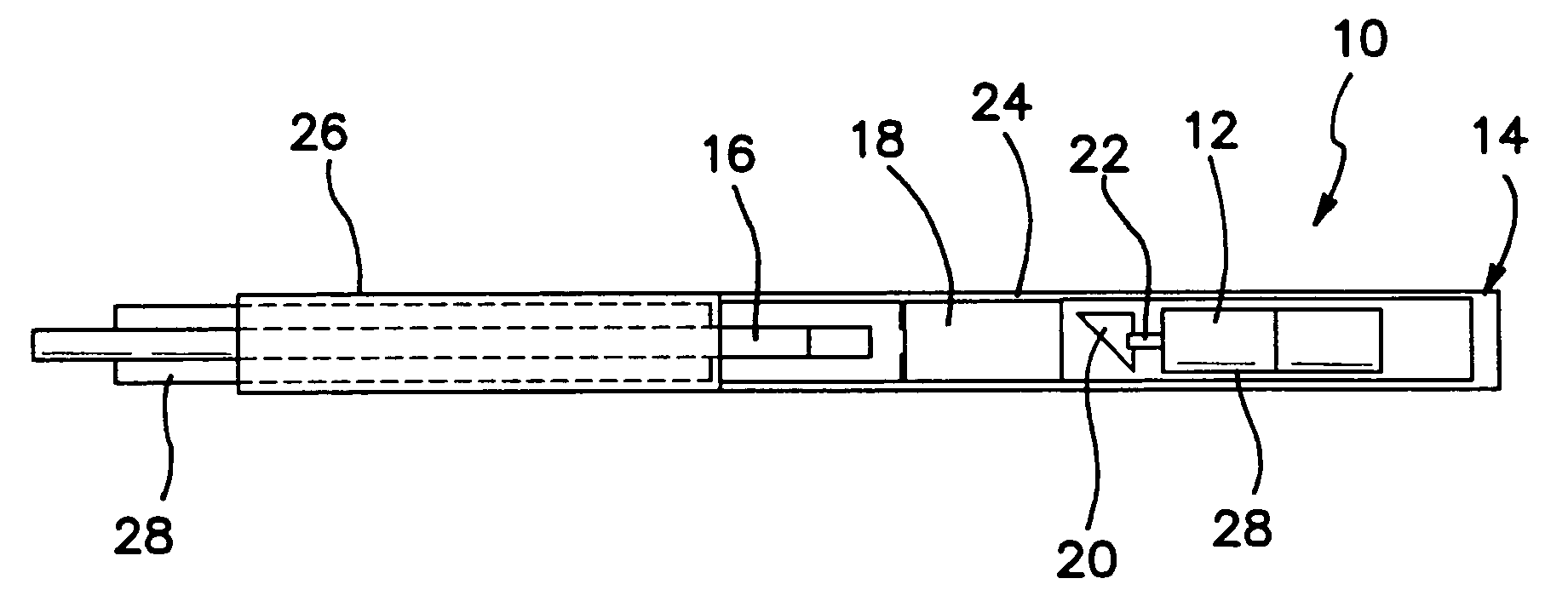
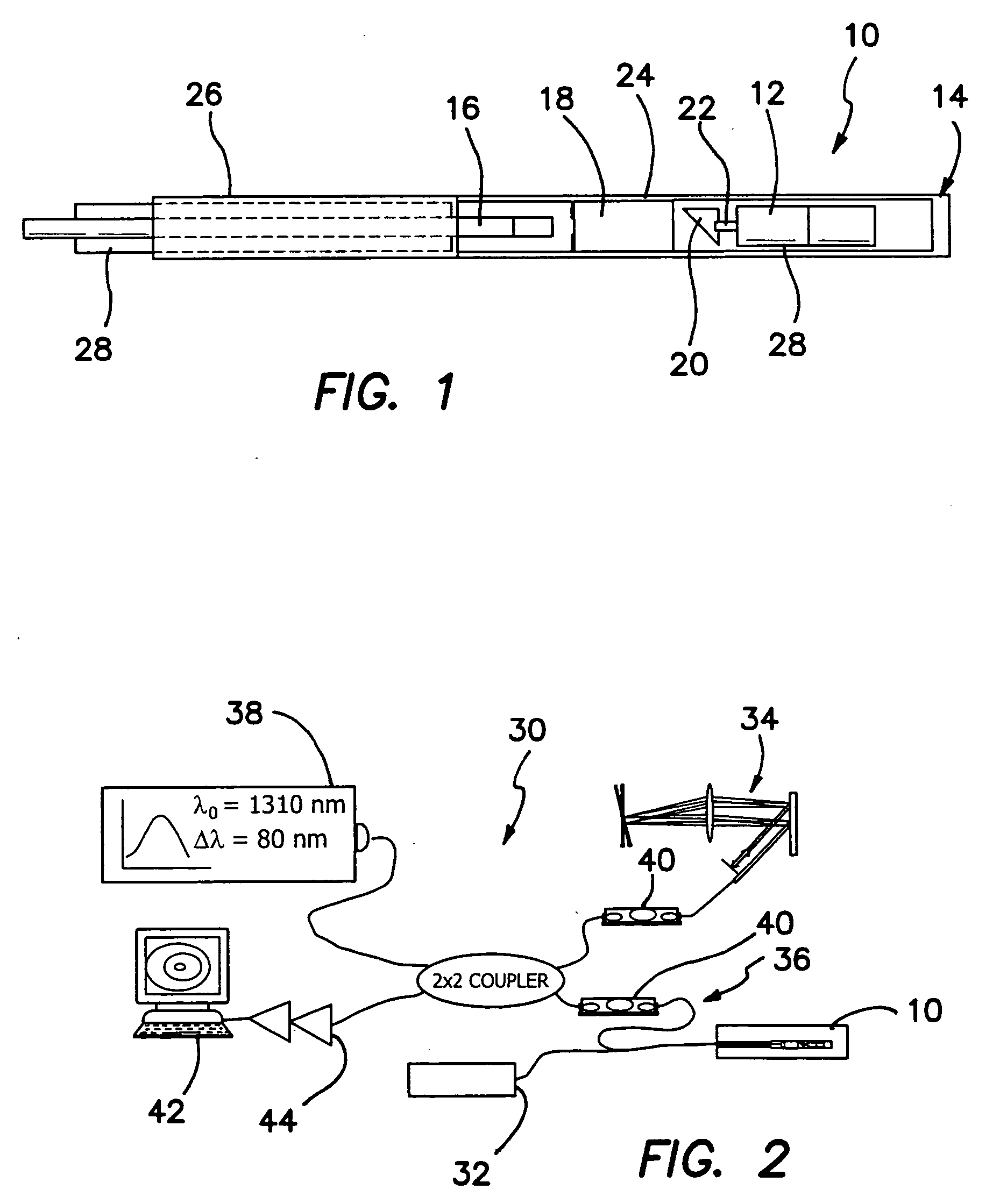
[0037] The current invention overcomes each of the limitations of the prior art by using a microelectromachined silicon (MEMS) motor 12 near the tip 14 of the endoscope 10 to perform the scanning. No driving cable is required or used. A side cut-away plan view of the distal end portion of the illustrated embodiment of the endoscope 10 is shown in FIG. 1. The design of endoscope 10 is much simpler than the prior art designs. A single mode optical fiber 16 with or without a tapered tip is mounted to the GRIN lens 18 at the appropriate distance. A prism 20, which has a diameter or radial envelope within endoscope 10 smaller than the diameter of motor 12 is mounted on a shaft 22 or otherwise coupled to motor 12. In the preferred embodiment motor 12 provides a full rotary motive force or torque applied through shaft 22 to the prism 20. However, it is expressly contemplated that motor 12 will also supply an oscillatory motive force or torque to prism 20 through a predetermined angular int...


PUM


Abstract

An endoscopic probe is combined with a source of radiation to measure a sample. A probe body includes a nonrotating transmission path and is communicated to the source to transmit radiation from the source from the proximal to the distal portion of the probe body. A micromotor is disposed in a distal portion of the probe body to provide a motive force. A movable scanner is coupled to the motor and is arranged and configured so that the scanner is directed toward or faces the transmission path. The scanner redirects the radiation from the source from the distal portion of the probe body into a scanned pattern onto the sample according to the motive force applied to the scanner from the motor. Back reflected radiation is received from the sample and is transmitted along the transmission path to the proximal portion of the probe body.

Description

RELATED APPLICATIONS [0001] The present application is related to U.S. Provisional Patent Application Ser. No. 60 / 509,965, filed on Oct. 9, 2003, which is incorporated herein by reference and to which priority is claimed pursuant to 35 USC 119.GOVERNMENT SUPPORT [0002] This invention was made with Government Support under Grant No. BES-0086924, awarded by the National Science Foundation. The Government has certain rights in this invention.BACKGROUND OF THE INVENTION [0003] 1. Field of the Invention [0004] The invention relates to the field of endoscopic probes and in particular to endoscopic probes used for optical coherence tomography (OCT). [0005] 2. Description of the Prior Art [0006] Direct visualization of tissue anatomy and physiology provides important information to the physician for the diagnosis and treatment of disease. Noninvasive techniques with high spatial resolution for tomographic imaging of in vivo tissue structure and physiology are currently not available as a di...

Claims


Application Information

Patent Timeline
Patent Type & Authority Applications(United States)
IPC IPC(8): A61B1/07
CPCA61B5/6852A61B5/0066
Inventor CHEN, ZHONGPINGTRAN, PETER
Owner C&L CONSULTING
Why Eureka
Try Eureka