Method and device for determining the aerodynamic wall shear stresses on the surface of a body around wich air flows

a technology of aerodynamic wall and shear stress, which is applied in the direction of instrumentation, electric digital data processing, structural/machine measurement, etc., and can solve problems such as inapplicability continuously

Inactive Publication Date: 2005-06-30
EADS DEUT GMBH
View PDF11 Cites 16 Cited by
  • Summary
  • Abstract
  • Description
  • Claims
  • Application Information

AI Technical Summary

Benefits of technology

[0013] In reversible and laminar methods and devices, the wall shear stress measurements for different measuring points and measurement series are carried out in a continuous and surface-covering manner. This means in particular that the wall shear stress measurements for different measuring points and measurement series take place without having to shut down the wind tunnel between individual measuring points to carry out applications on the model.
[0015] The combination of infrared thermography methods (IRT) and methods of the optical pressure measuring technique (PSP) makes it possible to determine wall shear stresses continuously during the running test via the Reynolds analogy. Furthermore, the PSP pressure image can be corrected by the temperature information (IR camera). According to the invention, a combination of both measuring techniques (IR and PSP) via the Reynolds analogy is provided. According to the invention, the wall shear stress is determined indirectly via a heat flow from the model to the fluid and vice versa. By applying the inventive measuring method, it is possible to determine the local speed at the model in addition to the local heat flow and, by an extended Reynolds analogy, to metrologically determine the wall shear stress also on three-dimensional wind tunnel models.

Problems solved by technology

The disadvantage of these methods and devices is that these methods only allow results by making wall shear stresses visible and, furthermore, are not applicable continuously.

Method used


Image

  • Method and device for determining the aerodynamic wall shear stresses on the surface of a body around wich air flows
  • Method and device for determining the aerodynamic wall shear stresses on the surface of a body around wich air flows
  • Method and device for determining the aerodynamic wall shear stresses on the surface of a body around wich air flows

Examples


Embodiment Construction

[0026] The particulars shown herein are by way of example and for purposes of illustrative discussion of the embodiments of the present invention only and are presented in the cause of providing what is believed to be the most useful and readily understood description of the principles and conceptual aspects of the present invention. In this regard, no attempt is made to show structural details of the present invention in more detail than is necessary for the fundamental understanding of the present invention, the description taken with the drawings making apparent to those skilled in the art how the several forms of the present invention may be embodied in practice.

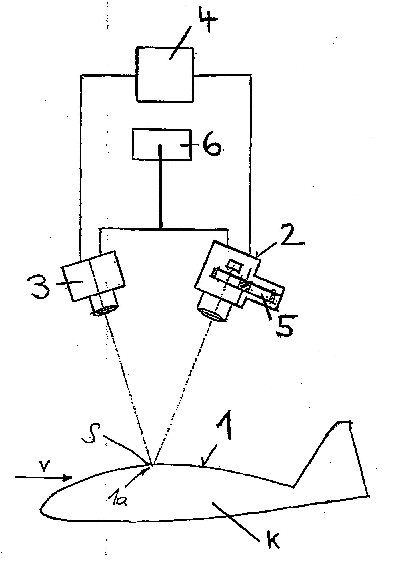
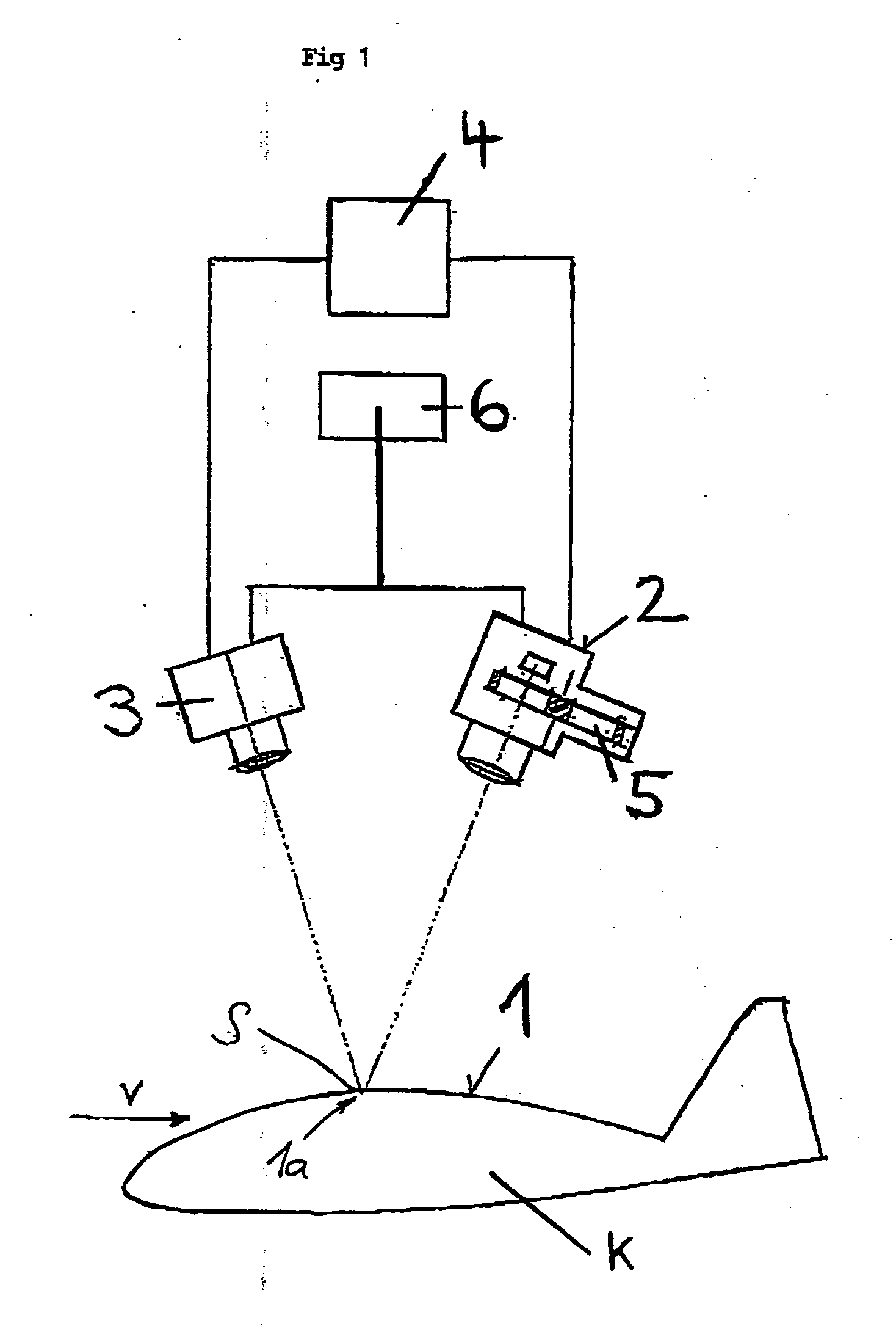
[0027] According to the invention, physical state parameters are determined, in particular the wall shear stress and the heat flow or the temperature distribution on a surface 1 or a zone 1a of a body K around which air flows. In the area of the measuring zone 1a, the body K is provided with a measuring layer S that is ...


PUM

PropertyMeasurementUnit
wall shear stress distributionaaaaaaaaaa
surface pressure distributionaaaaaaaaaa
optical pressure measuringaaaaaaaaaa

Abstract

A method for determining a wall shear stress distribution on a surface of a body around which air flows. The method includes determining a heat flow distribution into the surface of the body around which air flows by infrared thermography, obtaining a surface pressure distribution on the surface optically and determining the wall shear stress distribution on the surface of the body by processing from at least the heat flow distribution and the surface pressure distribution. The instant abstract is neither intended to define the invention disclosed in this specification nor intended to limit the scope of the invention in any way.

Description

CROSS-REFERENCE TO RELATED APPLICATIONS [0001] The present application is a Continuation of International Application No. PCT / DE03 / 01797, filed on Jun. 3, 2003 and claims priority of German Patent Application No. DE 102 25 616.0, filed on Jun. 7, 2002. Moreover, the disclosure of International Patent Application No. PCT / DE03101797, filed on Jun. 3, 2003 is expressly incorporated by reference herein in its entirety.BACKGROUND OF THE INVENTION [0002] 1. Field of the Invention [0003] The invention relates to a method and a device for determining the aerodynamic wall shear stresses on the surface of a body around which air flows. [0004] 2. Discussion of Background Information [0005] Methods and devices for determining aerodynamic wall shear stresses on the surface of a body around which air flows are known from the general prior art, in which methods and devices these are determined optically by oil-paint methods or pressure sensitive paint (PSP) layers, whereby the luminophore was “was...

Claims


Application Information

Patent Timeline
Patent Type & Authority Applications(United States)
IPC IPC(8): G01L1/00G01L1/24G01M9/06
CPCG01M9/062G01L1/248
Inventor SCHULZE, BERNDTRINKS, OLE
Owner EADS DEUT GMBH
Why Eureka
Try Eureka