Method and apparatus for control of hydraulic systems

a hydraulic system and control method technology, applied in the direction of fluid couplings, clutches, coupling combinations, etc., can solve the problems of insufficient performance, workpiece overground or overdrilled, and lack of small-scale control of the system

Inactive Publication Date: 2005-07-07
HIGH COUNTRY TEK
View PDF6 Cites 21 Cited by
  • Summary
  • Abstract
  • Description
  • Claims
  • Application Information

AI Technical Summary

Benefits of technology

[0006] Programming takes place through a graphical user interface on a computer (or other input device). The program is in a visual format, allowing the user to specify several nodes through which the sequence travels and the transitional sequences that direct the path from one node to another. The input / output profile is depicted graphically, and the user may adjust the curve itself by adjusting the points on the curve. Adjustments may also be made while the controller is running. Thus, control of nonlinear response or of output having unknown characteristics may be achieved. Flash memory allows reprogramming in the field.
[0009] It is a further object of the present invention to provide a method and apparatus as characterized above utilizing a graphical user interface that may be programmed by a user without advanced knowledge of high-level programming languages, and thus avoids high outside programming costs.
[0011] It is a further object of the present invention to provide a method and apparatus as characterized above that allows a user to control both high and low sides of an attached valve coil.
[0012] It is a further object of the present invention to provide a method and apparatus as characterized above that is versatile with respect to acceptable input forms.

Problems solved by technology

The major problem attending control of such devices is the lack of small-scale control of the systems.
Lack of small-scale control results in damage: trees shaken too hard are uprooted; garbage cans set down too hard crack under the force; and workpieces are overground or overdrilled.
Unfortunately, smart controllers are rare, and, if unable to be modified subsequently, must of necessity define parameters based on extreme conditions, which is inefficient, since it can lead to oversizing, overpowering, or worse, inadequate performance.

Method used


Image

  • Method and apparatus for control of hydraulic systems
  • Method and apparatus for control of hydraulic systems
  • Method and apparatus for control of hydraulic systems

Examples


Embodiment Construction

[0050] Considering the drawings, wherein like reference numerals denote like parts throughout the various drawing figures, reference numeral 10 is directed to the control system according to the present invention.

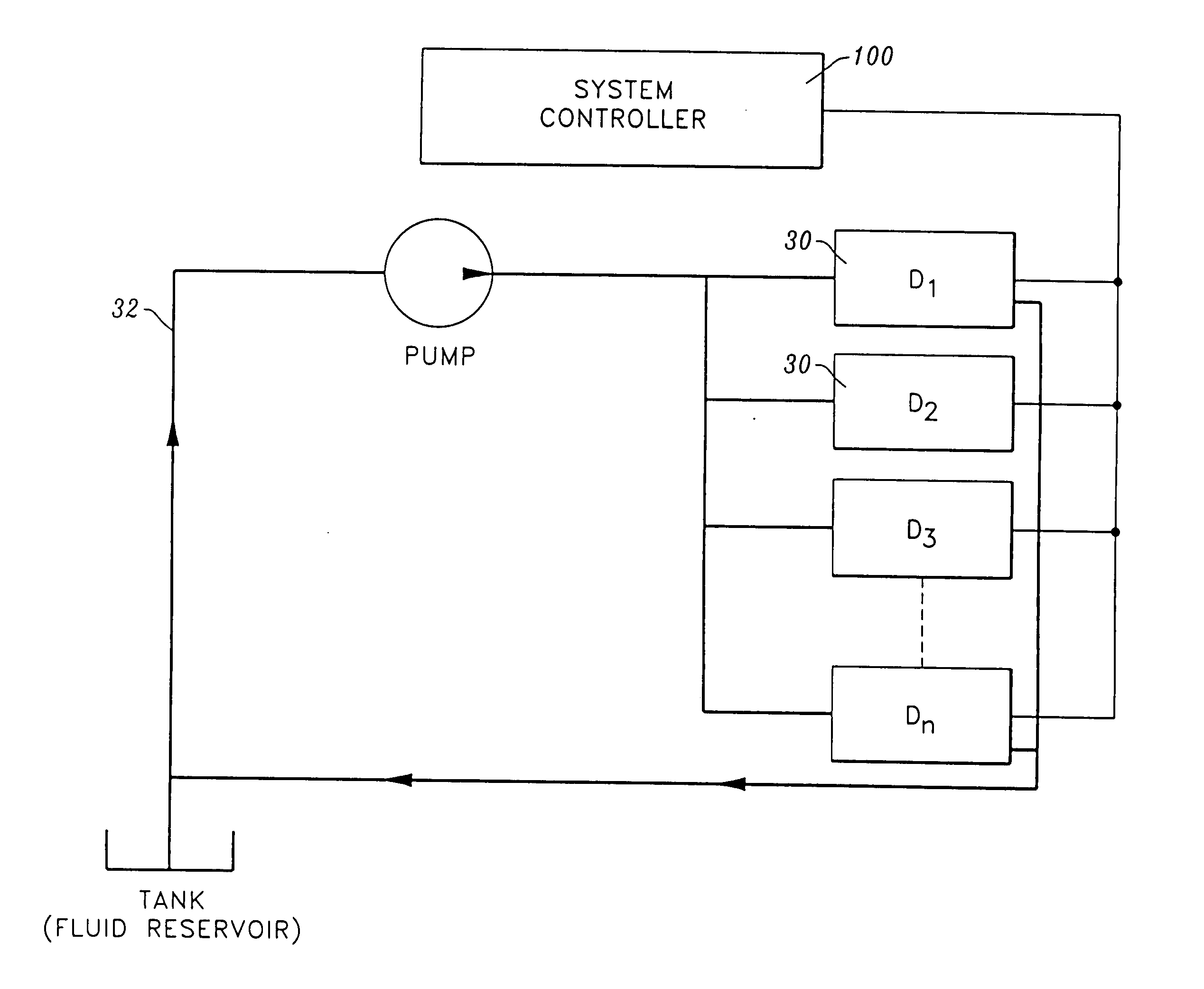
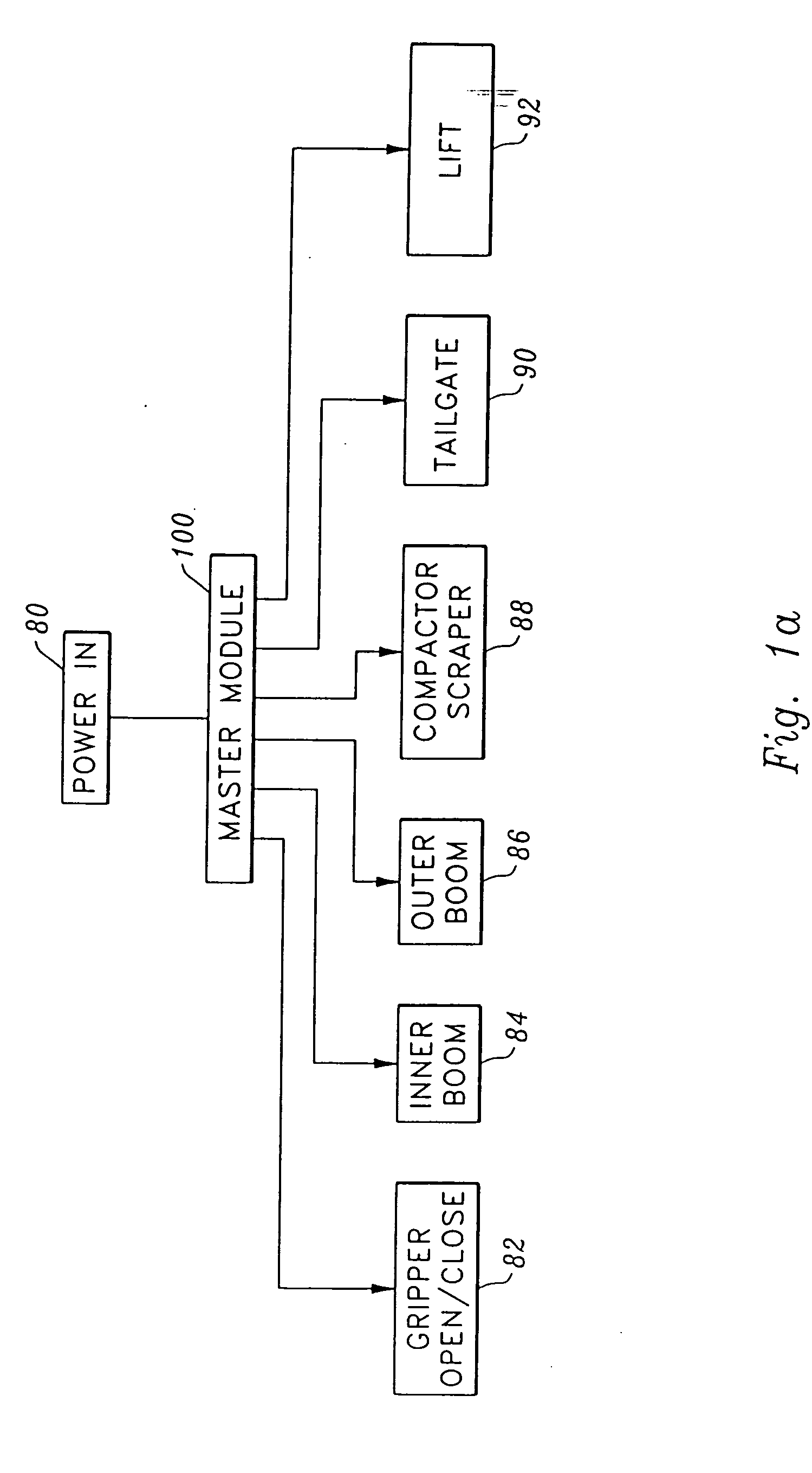
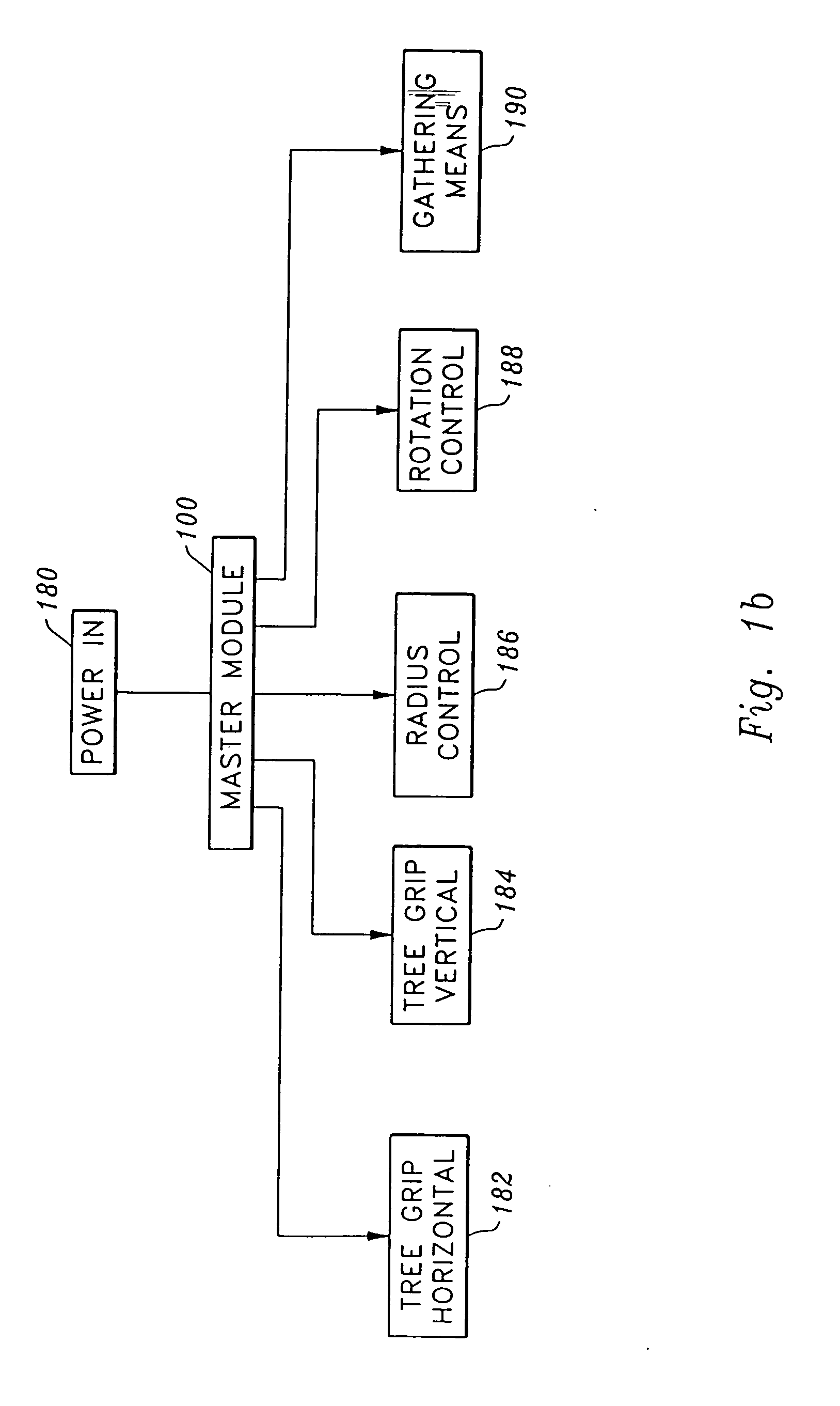
[0051] In its essence, the control system 10 is comprised of a master module 100 having multiple inputs 106, including analog, digital, and universal inputs. Universal inputs are programmable; they accept input from various types of sensors. Outputs 104 on the master module 100 include both on / off and proportional outputs. These outputs 104 allow a multitude of different output configurations to be programmed. LED indicator lights 110a-g on the master module 100 display the status of the various connections. The master module 100 may be used on its own or it may be combined with a plurality of slave modules 200a-h for control over a larger system (FIG. 4), preferably on a DeviceNet-compatible CAN Bus system.

[0052] Master module 100 is programmable by use of a graphical pr...


PUM


Abstract

An apparatus and method for controlling hydraulic systems. The control apparatus (module) accepts a variety of input forms, and the output is user-configurable to control both sides of an attached coil. The master module is programmable via a graphical user interface defining states and conditions triggering transitions between states. The master module may be combined with slave modules on a connection bus to control many subsystems. Reprogramming of the master module may occur in the field by use of flash memory, and input / output characteristics may be adjusted during operation of the system, allowing adjustment of systems exhibiting nonlinear response characteristics.

Description

FIELD OF THE INVENTION [0001] The following invention relates generally to methods of and apparatus for controlling systems utilizing hydraulic power. More specifically, the instant invention relates to hydraulic control of multiple systems including resetting hydraulic parameters according to a flexible rule set. BACKGROUND OF THE INVENTION [0002] Typical systems under hydraulic control encompass a huge universe and include garbage trucks, nut harvesters, rock crushers, tub grinders, drilling machines, compactors, and grape harvesters. Control systems for hydraulic devices such as these have been developed and are currently in use. The major problem attending control of such devices is the lack of small-scale control of the systems. Large-scale control is simple: lifting, lowering, shaking, etc. Small-scale control can be analogized to fine motor control in humans, e.g., how much force to use when setting something down, or how much force to use when shaking fruit or nuts from a tr...

Claims


Application Information

Patent Timeline
Patent Type & Authority Applications(United States)
IPC IPC(8): F15B19/00F15B21/02
CPCF15B21/02F15B19/002
Inventor HULSE, ROBRASMUS, BRUCETETZLAFF, BRIAN
Owner HIGH COUNTRY TEK
Why Eureka
Try Eureka