
System and method for valve actuation

a valve and actuator technology, applied in the direction of non-mechanical valves, valve drives, machines/engines, etc., can solve the problems of increasing the cost of the vehicle, increasing the space required for the system, and creating packaging and manufacturing concerns

Active Publication Date: 2005-07-07
JACOBS VEHICLE SYST
View PDF12 Cites 12 Cited by
  • Summary
  • Abstract
  • Description
  • Claims
  • Application Information

AI Technical Summary

Benefits of technology

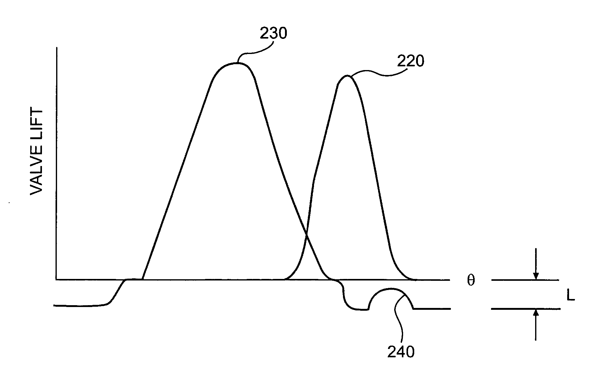
[0012] An advantage of embodiments of the present invention is that engine intake and exhaust valves may be opened and closed by fixed profile cams, and more specifically by one or more fixed lobes which may be an integral part of each of the cams. Using, for example, an EGR lobe ground into the cam of the same engine cylinder where the valve event is to occur may significantly reduce packaging difficulties. Other benefits such as increased performance, improved fuel economy, lower emissions, and better vehicle drivability may be obtained by optimizing the engine valve timing and lift.

Problems solved by technology

These additional components may significantly increase the cost of the vehicle, and may increase the space required for the system, creating packaging and manufacturing concerns.
Some “cross-actuated” EGR systems, however, may be difficult to package within the constraints of a vehicle.
The use of fixed profile cams, however, can make it difficult to adjust the timings and / or amounts of engine valve lift to optimize them for various engine operating conditions.

Method used


Image

  • System and method for valve actuation
  • System and method for valve actuation
  • System and method for valve actuation

Examples


Embodiment Construction

[0024] Reference will now be made in detail to embodiments of the system and method of the present invention, examples of which are illustrated in the accompanying drawings. As embodied herein, the present invention includes systems and methods of controlling the actuation of engine valves.

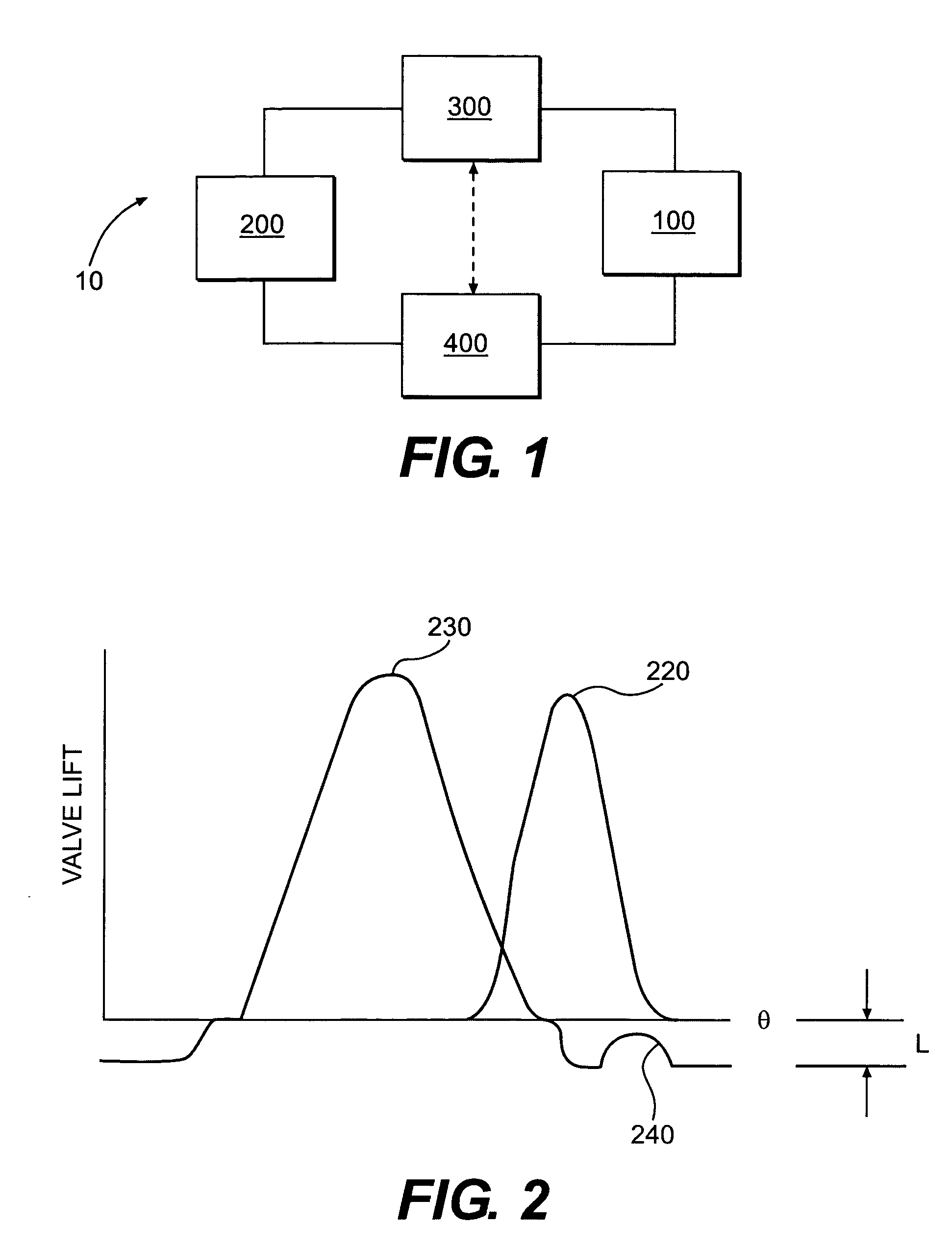
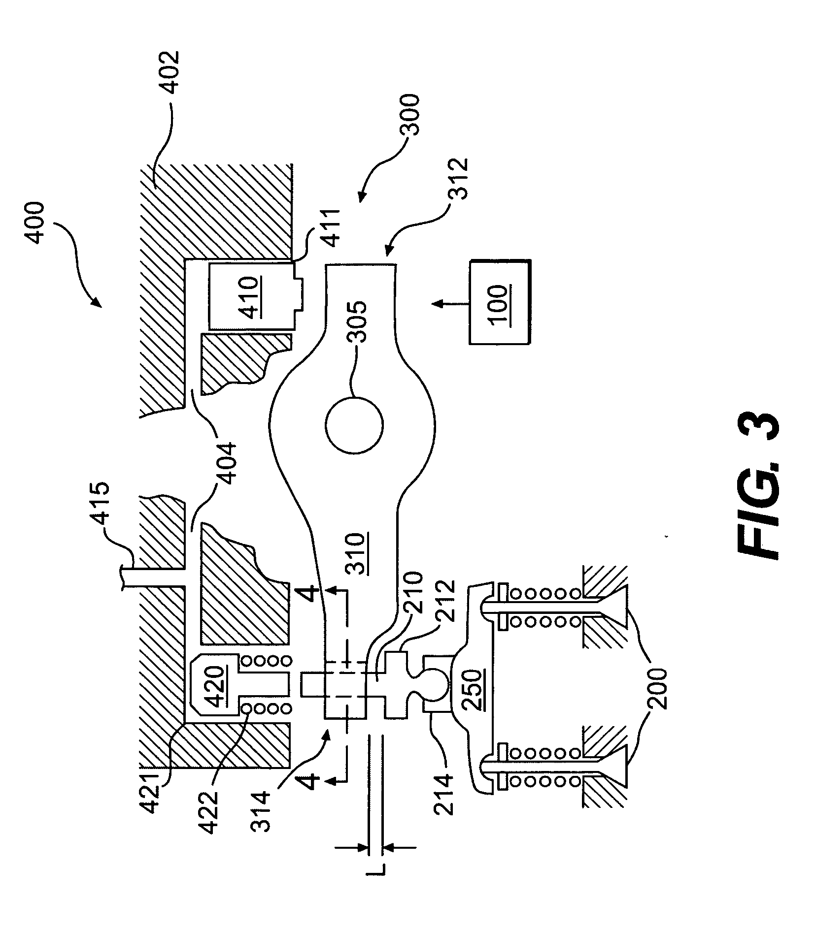
[0025] An embodiment of the present invention is shown schematically in FIG. 1 as valve actuation system 10. The valve actuation system 10 includes a means for imparting a valve train motion 100 to one or more engine valves 200, a first valve actuation subsystem 300 and a second valve actuation subsystem 400. The motion imparting means 100 is operatively connected to the first valve actuation subsystem 300, which in turn selectively actuates the engine valves 200. The first valve actuation subsystem 300 is operatively connected to the second valve actuation subsystem 400, which in turn selectively actuates the engine valves 200. The first valve actuation subsystem 300 and the second valve actuati...


PUM


Abstract

The present invention is directed to a system and method for actuating an engine valve. In one embodiment, the present invention is a system for providing exhaust gas recirculation (EGR) in an engine having at least one engine valve, the system comprising: means for imparting a valve train motion; a first valve actuation subsystem for transferring motion from the motion imparting means to the engine valve, the first valve actuation subsystem capable of providing valve actuation for at least a portion of a main exhaust event during a first engine operating condition, and a full main exhaust event during a second engine operating condition; and a second valve actuation subsystem for transferring motion from the motion imparting means to the engine valve, the second valve actuation subsystem capable of providing valve actuation for an exhaust gas recirculation event during the first engine operating condition.

Description

CROSS-REFERENCE TO RELATED APPLICATION [0001] This application claims priority on U.S. Provisional Patent Application Ser. No. 60 / 532,889, for System and Method for Valve Actuation, filed on Dec. 30, 2003, the entirety of which is incorporated herein by reference.FIELD OF THE INVENTION [0002] The present invention relates generally to a system and method for actuating one or more valves in an engine. In particular, the present invention relates to systems and methods for actuating one or more engine valves to produce an engine valve event such as, for example, a main valve event (exhaust and / or intake), a compression release braking event, a bleeder braking event, an exhaust gas recirculation event, and / or other auxiliary valve events. BACKGROUND OF THE INVENTION [0003] Valve actuation in an internal combustion engine is required in order for the engine to produce positive power, engine braking, and exhaust gas recirculation (EGR). During positive power, one or more intake valves ma...

Claims


Application Information

Patent Timeline
IPC IPC(8): F01L9/10F01L13/06F02D13/04F02M25/07
CPCF01L1/08F01L1/181F01L1/26Y02T10/121F01L13/065F02D13/04F02M25/0752F01L9/02F02M26/01F01L9/10F01L13/00
Inventor YANG, ZHOURUGGIERO, BRIAN
Owner JACOBS VEHICLE SYST
Learn More