Calibration method for the correction of in-phase quadrature signal mismatch in a radio frequency transceiver

a radio frequency transceiver and phase quadrature technology, applied in the direction of transmission, electrical equipment, etc., can solve the problems of frequency but also simultaneously generating another unwanted frequency, corresponding amplitude and phase mismatch, and modulated signals are made more difficult to accurately detect in the presence of nois

Inactive Publication Date: 2005-07-07
FODUS COMM
View PDF3 Cites 58 Cited by
  • Summary
  • Abstract
  • Description
  • Claims
  • Application Information

AI Technical Summary

Problems solved by technology

That is, during the frequency conversion process, the mixer not only generates a desired frequency but also simultaneously generates another unwanted frequency.
In practice, a variety of unavoidable circuit hardware tolerances exist resulting in a corresponding amplitude and phase mismatch.
As a result, the modulated signals are made more difficult to accurately detect in the presence of noise.
The symbol error rate of the receiver portion will increase and degrade the overall RF transceiver performance.
IQ mismatches in the LO signals are common due to the difficulty of precisely matching amplitude and phase of high frequency RF signals on integrated circuits (IC).
While circuit techniques exist to mix or separate quadrature components of an RF signal, finite degree of matching of IC components, parameter variations over temperature and from IC processing and unavoidable imperfections such as parasitics from physical layout prevent the achievement of perfect IQ matching.
Often times, the actual value of achievable IRR cannot be predicted or is not known until after the IC has been fabricated and characterized.
In practice, this approach is difficult to implement as the detector circuits operate at high frequencies and are themselves sensitive to various circuit parameter mismatches and process variations.
Additionally, precise gain and phase adjustment circuits are difficult to realize at high frequencies.
Once again, a high degree of circuit complexity is required to implement this solution and it will still be sensitive to unavoidable imperfections such as circuit parameter mismatches, DC offsets and process variations.
However, the key obstacle to this approach is the formulation of a method by which to accurately measure the IQ mismatch.
Directly measuring IQ mismatch is difficult to do in high frequency analog circuits.
Likewise, indirectly measuring IQ mismatch through the metric of IRR is also difficult as this requires an ideal demodulator that is essentially free of IQ mismatches and does not degrade the IRR itself.
Unfortunately, the receiver circuit of the IC itself can not be an ideal demodulator and will exhibit the same finite image rejection ratio as that of the transmitter thus making it difficult to get an accurate measurement of the IRR of the transmitter only.

Method used

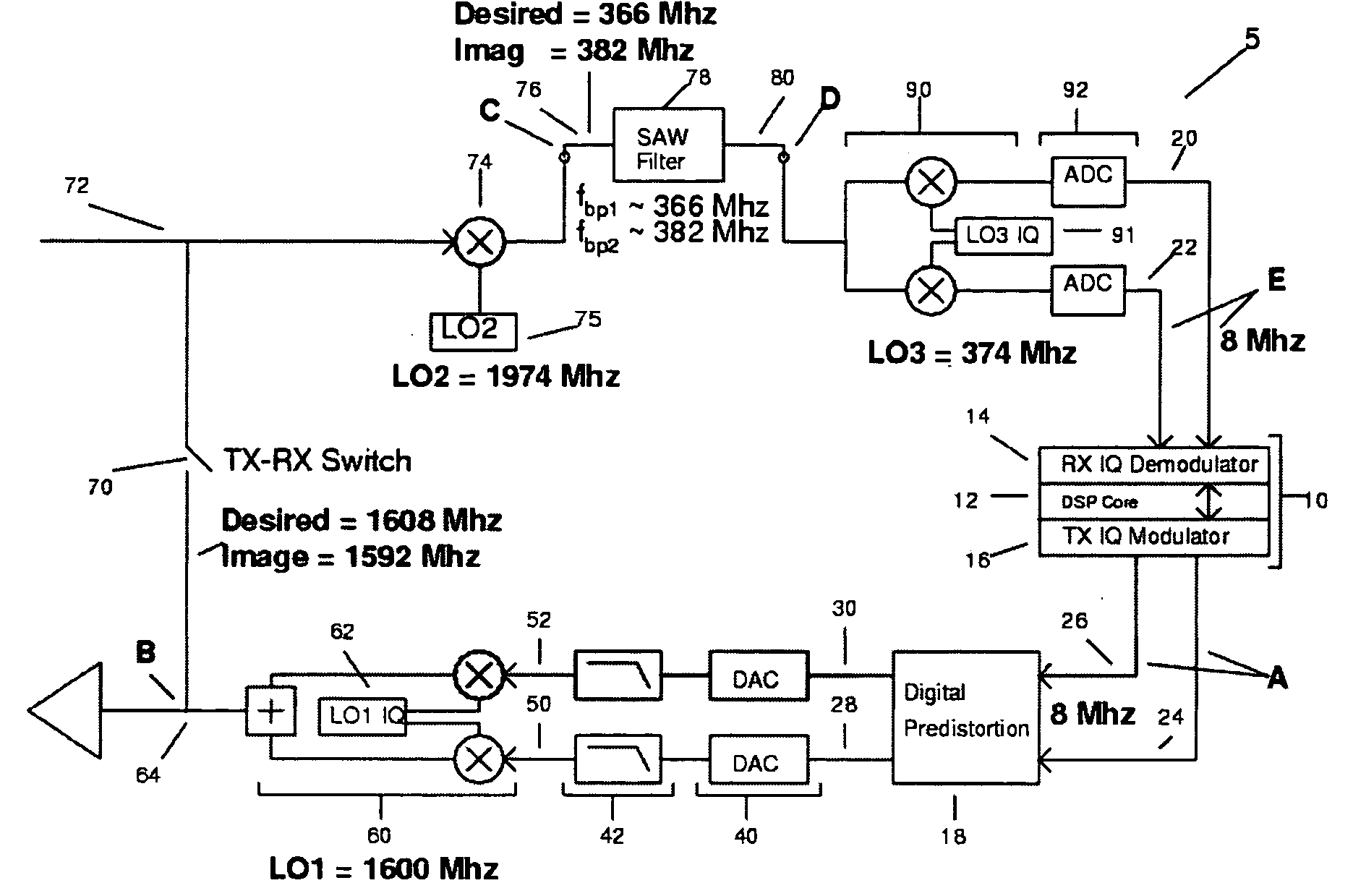
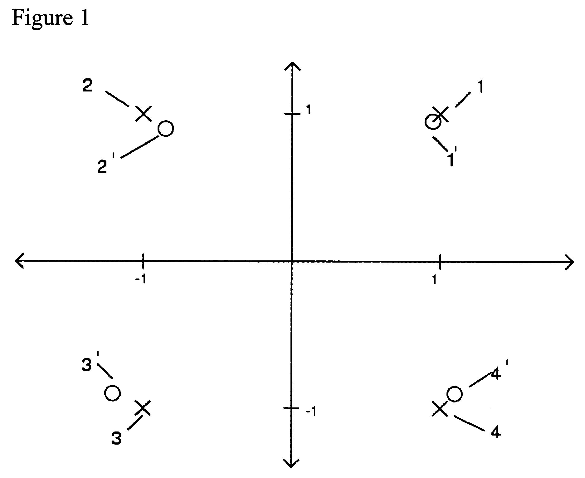
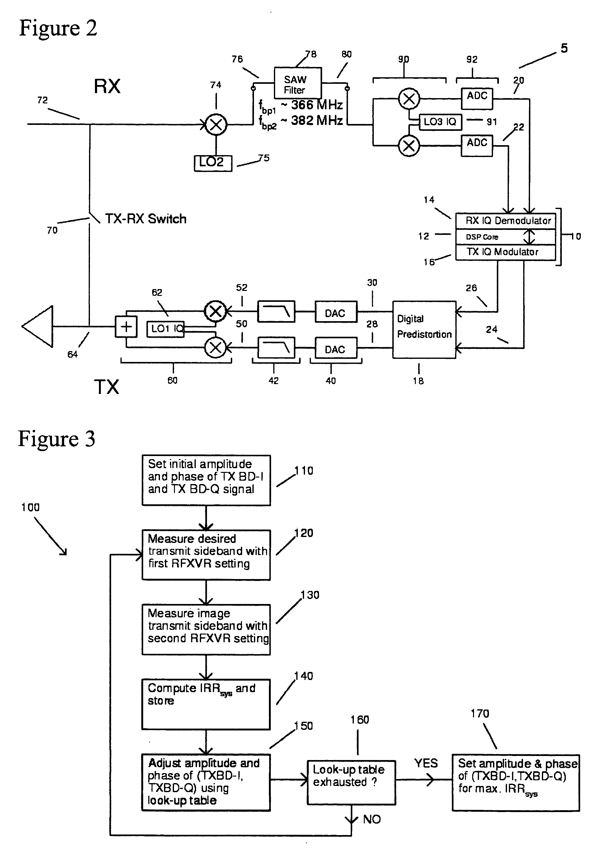

Image

  • Calibration method for the correction of in-phase quadrature signal mismatch in a radio frequency transceiver
  • Calibration method for the correction of in-phase quadrature signal mismatch in a radio frequency transceiver
  • Calibration method for the correction of in-phase quadrature signal mismatch in a radio frequency transceiver

Examples


Embodiment Construction

[0041] In the following detailed description of the present invention, numerous specific details are set forth in order to provide a thorough understanding of the present invention. However, it will become obvious to those skilled in the art that the present invention may be practiced without these specific details. In other instances, well known methods, procedures, components, and circuitry have not been described in detail to avoid unnecessary obscuring aspects of the present invention. The detailed description is presented largely in terms of flow charts, logic blocks and other symbolic representations that directly or indirectly resemble the operations of signal processing devices coupled to networks. These descriptions and representations are the means used by those experienced or skilled in the art to concisely and most effectively convey the substance of their work to others skilled in the art.

[0042] Reference herein to “one embodiment” or an “embodiment” means that a parti...


PUM


Abstract

A method is disclosed to correct the IQ mismatch of an RF transceiver. The method generates a reference signal down a transmitting-receiving loop and measures the received signals SDTA-1 and SDTA-2, respectively dominated by their desired component and image component, under two programmed mixer settings of operating mode and LOF. The method then calculates a system image rejection ratio (IRRsys) with SDTA-1 and SDTA-2, systematically adjusts the amplitude and phase pre-distortion of the transmitting baseband signals till IRRsys is maximized thus correcting for the transmitter IQ mismatch. The now-corrected transmitter IQ mismatch is then used to correct receiver IQ mismatch by reprogramming the first setting and measuring mismatches in amplitude ΔA and phase Δφ between received baseband IQ signals, corrects for ΔA and Δφ accordingly and stores the corrective values for future compensation of receiver IQ mismatch. The systematic pre-distortion can be implemented using a look-up table or analytical calculation.

Description

CROSS REFERENCE TO RELATED APPLICATIONS [0001] This application is related to the U.S. patent application Ser. No. 10 / 447,810, filed 05 / 28 / 2003, entitled “Wireless LAN receiver with packet level automatic gain control” by Steve S. Yang, assigned to the same assignee, which is herein incorporated by reference. FIELD OF THE INVENTION [0002] The present invention relates generally to the field of wireless communication. More particularity, the present invention concerns the calibration of a radio frequency (RF) transceiver. BACKGROUND OF THE INVENTION [0003] RF transceivers for wireless LAN systems generally use complex digital modulation schemes in order to achieve high data rates with limited bandwidth. Some examples are BPSK, 4-QPSK, 8-PSK, 16-PSK, 8-QAM, 16-QAM and 64-QAM. QAM, or quadrature amplitude modulation, is one such efficient digital modulation scheme. With QAM, data symbols are mapped into baseband in-phase (I) and quadrature (Q) modulated component signals. To facilitate...

Claims


Application Information

Patent Timeline
Patent Type & Authority Applications(United States)
IPC IPC(8): H04B1/10H04B1/30H04B1/40H04B1/44
CPCH04B1/30
Inventor JERNG, ALBERT CHIA-WEN
Owner FODUS COMM
Why Eureka
Try Eureka