Enhanced graphic features for computer assisted surgery system

a computer assisted surgery and enhanced technology, applied in the field of enhanced graphics capabilities of computer assisted surgery systems, can solve the problems of difficult to accurately predict the placement of the final guide pin, difficult to achieve the desired triangular spacing and optimal placement of the guide pin in the femoral neck, and t permit the surgeon much flexibility to modify the preset pattern, etc., to achieve the effect of improving the function of the instrument, promoting simple instruments, and sufficiently simulating

Inactive Publication Date: 2005-07-07
GE MEDICAL SYST GLOBAL TECH CO LLC
View PDF17 Cites 51 Cited by
  • Summary
  • Abstract
  • Description
  • Claims
  • Application Information

AI Technical Summary

Benefits of technology

[0008] Accordingly, one objective of the present invention is to provide a computer assisted surgery system with enhanced graphic features for assisting a surgeon in positioning multiple guide pins in a bone as part of a hip fracture fixation surgery and in orienting an acetabular cup during a total hip replacement surgery.
[0011] Still another objective of the invention is a method and apparatus for accurately orienting an acetabular component relative to the pelvis in a total hip replacement surgery.
[0014] The first enhancement is inclusion in the instrument representation of features that are not physically present on the instrument, but that provide additional information and functionality to the surgeon. While these virtual features are visible only in the graphic representation, their poses are related to the poses of real features of the instrument and their poses in space can be calculated. A virtual feature may represent a physical feature that is typically present on a conventional instrument but removed in the instrument under consideration. A virtual feature may also represent a physical feature that would improve the function of an instrument but cannot be added, or are not desirable to add, because of physical constraints, instrument simplicity, or other reasons (e.g., a long probe tip for indicating points inside of tissues) but whose function instead can be sufficiently simulated with appropriate modeling in the instrument's graphic representation. Further, virtual features may include modeling of physical features that are present on physical instruments at other times during the surgery or modeling of physical features that are located at other poses during other steps of the surgery and are related in position to the instrument being used in the current step (e.g., guide pin trajectories of past or future steps of the procedure). The representation of features virtually instead of physically allows the surgeon to benefit from the additional positioning information while still promoting simpler instruments and less invasive surgical technique.
[0015] The second enhancement to the graphics features is the ability to retain a version of the instrument representation on the display in the position that it occupied at a given point in time. This allows the surgeon to view representations of previously placed hardware (e.g., guide pins) without requiring the acquisition of new x-ray images. Further, virtual features may also be retained in order to carry over information from one step of the procedure to another (e.g., template information or planning markings) or to indicate the location of previously identified positions (e.g., selected landmarks or fiducials).
[0016] During the placement of guide pins in the hip fracture surgery, a drill guide is used with a graphic representation that comprises a real trajectory that corresponds to the bore of the drill guide and that shows the path a guide pin will take when inserted with the drill guide at its present position. The graphic representation further comprises one or more virtual trajectories that are defined relative to the real trajectory and represents other possible positions for guide pins. Preferably, the virtual trajectories are the other two positions of the desired triangular pattern of parallel guide pins typically used in femoral neck fracture fixation. The virtual trajectories can be redefined by the surgeon to achieve any desired pattern and spacing of the guide pins. During surgery, the surgeon uses the computer assisted surgery system to insert the first guide pin by aligning the pattern of real and virtual trajectories in an appropriate position over the x-ray images of the femoral head and neck. Subsequent guide pins are inserted by aligning the virtual trajectories with x-ray images of the femur and previously placed guide pins. Alternatively, representations of previously placed guide pins and virtual trajectories are retained and the subsequent guide pin placements are made by aligning the actual trajectory of the drill guide with the retained virtual trajectories. This invention has the advantages of assisting the surgeon in achieving a desired screw pattern, permitting a small incision with a single bore drill guide, and allowing the surgeon flexibility in placing the guide pins.
[0017] During the procedure to orient the acetabular cup, a probe is used to identify the location of three landmarks on the pelvis. The graphic representation of the probe includes a virtual tip, at a fixed and known distance from the real tip of the probe. Two roughly orthogonal x-ray views of the pelvis are obtained and the probe is moved, always above the skin, in the vicinity of the bony landmark, until a graphic representation of the virtual probe tip overlays the image of the landmark in both x-rays, and the 3-D position of the landmark is calculated. This process is preferably performed for both anterior superior iliac spines and the anterior pubis and a pelvic coordinate frame is established. A positioning instrument with attached acetabular cup is tracked by the localizer and the system provides both a graphic representation of the orientation of the acetabular cup over the x-ray images and an alphanumeric readout of two calculated angular orientation values familiar to the surgeon. This invention has the advantages of non-invasively identifying accepted landmarks for establishing a pelvic reference frame, of automatically registering the images, and of not requiring a CT scan prior to surgery.

Problems solved by technology

Some surgeons prefer to use a drill guide with a single bore, but doing so may make it difficult to achieve the desired triangular spacing and optimum placement of the guide pins in the femoral neck.
Other surgeons prefer a drill guide with multiple bores that are fixed in the proper triangular spacing, but this requires a larger incision and doesn't permit the surgeon much flexibility to modify the preset pattern.
With either drill guide, it can be difficult to accurately predict the final guide pin placement.
Further, the surgery requires a significant number of fluoroscopic images and x-ray exposure for the surgeon, patient and operating room staff.
These systems, however, do not provide help in selecting paths that will lead to the desired triangular pattern with proper spacing between screws.
On the other hand, a tracked drill guide with multiple bores may be used, but this requires a large incision and does not leave the surgeon with flexibility in the spacing or orientation (e.g., parallel vs. diverging) of the screws.
Cups that are not properly oriented can lead to dislocation of the new hip and may require reoperation to reorient the cup.
However, it can be quite difficult to orient the acetabular cup correctly.
This problem is even worse with obese patients.
Further, the pelvis may be tilted relative to the operating table, making it difficult to use the table or any vertical or horizontal plane as a reliable reference.
While this system can improve the accuracy, and even the surgical outcome of the total hip procedure, it requires a CT scan which is not currently required, and a potentially time consuming intraoperative registration step.

Method used


Image

  • Enhanced graphic features for computer assisted surgery system
  • Enhanced graphic features for computer assisted surgery system
  • Enhanced graphic features for computer assisted surgery system

Examples


Embodiment Construction

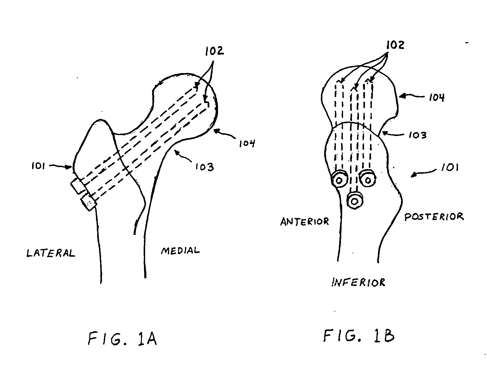
[0030] Current surgical practice for the treatment of a femoral neck fracture is the insertion of three cannulated screws through a small incision on the lateral (side) aspect of the hip. As shown in FIG. 1A, the screws (102) are inserted from the lateral aspect of the trochanteric area of the femur (101) through the femoral neck (103) and into the femoral head (104) in a roughly parallel manner. When observed from a lateral view, FIG. 1B, the screws describe the vertices of a triangle with one screw placed inferiorly (toward the knee), one placed anteriorly (toward the front) and one placed posteriorly (toward the back).

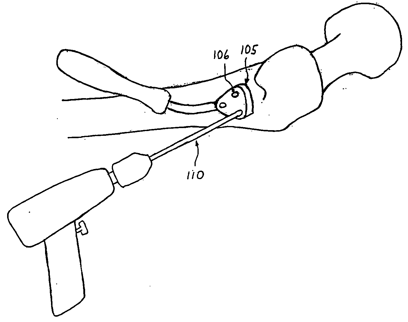
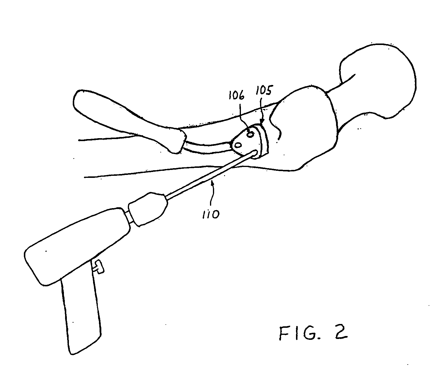
[0031] The first step of the procedure, shown in FIG. 2, is the insertion of three guide pins (110) under fluoroscopic guidance. Numerous x-ray images involving frequent reorientation of the fluoroscope are required to monitor the progress of the guide pin insertion in both AP (front-to-back) and lateral (side) views. A drill guide (105) with three or more holes (1...


PUM


Abstract

A computer assisted surgery system with is enhanced graphics features is described for assisting a surgeon in orthopaedic procedures. A system is described for use in inserting multiple guide pins in hip fracture surgery using a single bore drill guide that has a graphical representation comprising its real trajectory and one or more virtual trajectories, the virtual trajectories representing potential positions of other guide pins to be placed during the procedure. Additionally, representations of inserted guide pins and virtual trajectories may be retained on the display at their inserted positions for use in aligning subsequent guide pins. A system is also described for orientation of an acetabular cup in a total hip replacement surgery. During cup insertion, the surgeon is provided with information regarding the orientation of the cup with respect to a pelvic reference frame that is based on accepted pelvic landmarks. The positions of each landmark is calculated by the system when a probe with a virtual tip, separate from its physical tip, is overlaid on the landmark in roughly orthogonal images of the pelvis.

Description

RELATED APPLICATIONS [0001] This application is a divisional of U.S. application Ser. No. 09 / 683,104, filed Nov. 19, 2001, entitled “Enhanced Graphic Features For Computer Assisted Surgery,” which is hereby expressly incorporated herein in its entirety including the specification, claims, drawings and abstract.BACKGROUND OF THE INVENTION [0002] This invention relates to a computer assisted surgery system with enhanced graphics capabilities for use in inserting multiple screws into a hip fracture and orienting a total hip acetabular component. [0003] Fractures of the femoral neck, one kind of hip fracture, are a common injury of the elderly with over 150,000 such fractures occurring annually. The currently accepted treatment for mildly displaced femoral neck fractures is surgical fixation. In the procedure, three cannulated screws are inserted in the hip, from the lateral aspect of the femur, across the fracture site and into the femoral head. The initial step is the placement of thr...

Claims


Application Information

Patent Timeline
Patent Type & Authority Applications(United States)
IPC IPC(8): A61B17/17A61B19/00A61F2/34A61F2/46
CPCA61B17/1703A61F2002/4681A61B17/1742A61B19/50A61B19/52A61B19/5244A61B19/56A61B2019/507A61B2019/5255A61B2019/5268A61B2019/5291A61F2/34A61F2/4609A61F2/4657A61F2002/4623A61F2002/4632A61F2002/4668A61B17/1721A61B90/36A61B2034/2055A61B2034/2068A61B34/20A61B34/25A61B34/10A61B2034/107A61B2090/365A61F2/4603
Inventor KIENZLE, THOMAS C. III
Owner GE MEDICAL SYST GLOBAL TECH CO LLC
Why Eureka
Try Eureka