Systems and methods for reducing the effect of corruptive signals during nanoliter osmometry

a nanoliter osmometry and signal reduction technology, applied in the field of measuring the osmolarity of fluids, to achieve the effect of reliable osmolarity measurement, accurate osmolarity measurement, and quick and easy acquisition

Active Publication Date: 2005-07-07
OCUSENSE
View PDF7 Cites 7 Cited by
  • Summary
  • Abstract
  • Description
  • Claims
  • Application Information

AI Technical Summary

Benefits of technology

[0013] Osmolarity measurement of a sample fluid, such as a tear film, is achieved by depositing an aliquot volume of the sample fluid on a microchip having a substrate and a sample region of the substrate, wherein the volume of the sample fluid operatively covers a sufficient portion of the sample region such that the energy imparted to the sample fluid is detected from the sample region to produce an output signal that indicates osmolarity of the sample fluid. Thus, an osmolarity measurement of the sample fluid can be obtained from the detected energy of the sample volume. The aliquot-sized sample volume can be quickly and easily obtained, even from dry eye patients. An aliquot volume can comprise, for example, a volume of no more than 20 microliters (μL), but can be as little as 1 nL. An osmolarity sensor system can receive the microchip and sample volume, and can detect energy from the sample volume to display an accurate osmolarity measurement. In this way, a reliable osmolarity measurement can be obtained with minimum inconvenience and discomfort to a patient, without requiring a great deal of skill to obtain the measurement, and with a high degree of repeatability and accuracy.
[0014] In one aspect, corruptive signals that effect detection of the energy imparted to the sample fluid are addressed and handled such that accurate measurements can be obtained for sample sizes in which physical phenomena dominate the electrical profile of the sample over time. For example, the transient relaxation of an aliquot of fluid across the measuring electrodes can be modeled to separate mechanical effects on the measured voltage from the steady state electrical conductivity which relates to osmolarity. Further, the effect of evaporation, which is an unavoidable consequence of fluidic systems with an inherent air gap, whether the receiving substrate be comprised of top down array microchips, or microchannel systems with a dead volume, etc., can be accounted for using linear regression and curve fitting techniques.

Problems solved by technology

Further, the effect of evaporation, which is an unavoidable consequence of fluidic systems with an inherent air gap, whether the receiving substrate be comprised of top down array microchips, or microchannel systems with a dead volume, etc., can be accounted for using linear regression and curve fitting techniques.

Method used


Image

  • Systems and methods for reducing the effect of corruptive signals during nanoliter osmometry
  • Systems and methods for reducing the effect of corruptive signals during nanoliter osmometry
  • Systems and methods for reducing the effect of corruptive signals during nanoliter osmometry

Examples


Embodiment Construction

.”

BRIEF DESCRIPTION OF THE DRAWINGS

[0016] Features, aspects, and embodiments of the inventions are described in conjunction with the attached drawings, in which:

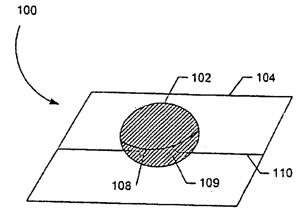
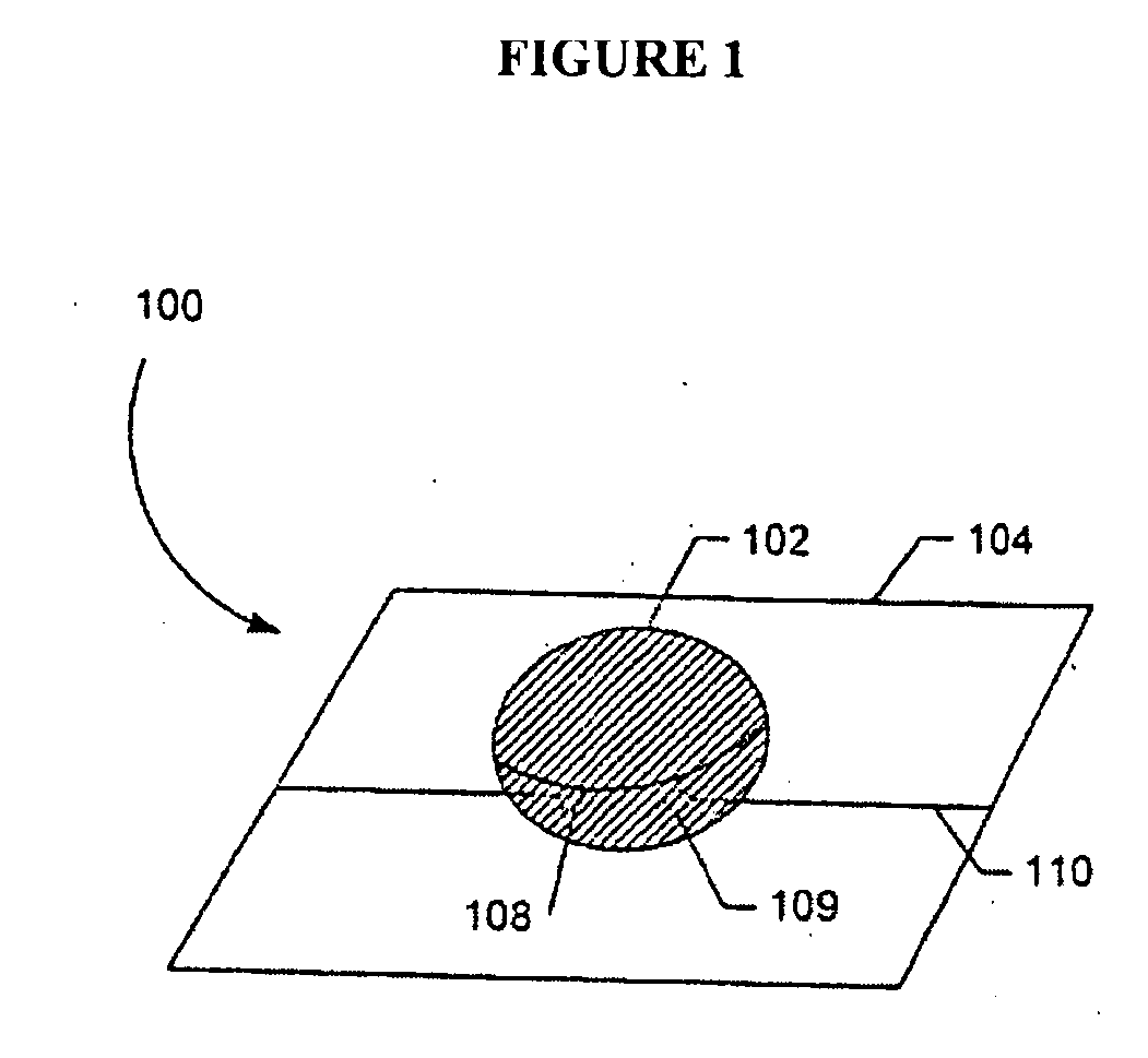
[0017]FIG. 1 illustrates an aliquot-sized sample receiving chip for measuring the osmolarity of a sample fluid.

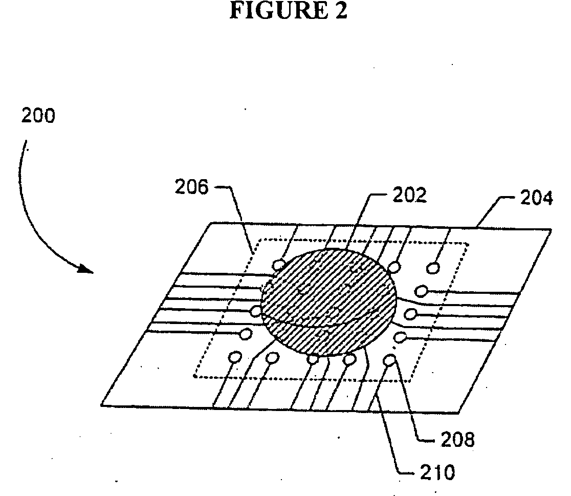
[0018]FIG. 2 illustrates an alternative embodiment of a sample receiving chip that includes a circuit region with an array of electrodes imprinted with photolithography techniques.

[0019]FIG. 3 illustrates another alternative embodiment of the FIG. 1 chip, wherein a circuit region includes printed electrodes arranged in a plurality of concentric circles.

[0020]FIG. 4 is a top view of the chip shown in FIG. 2.

[0021]FIG. 5 is a top view of the chip shown in FIG. 3.

[0022]FIG. 6 is a block diagram of an osmolarity measurement system configured in accordance with the present invention.

[0023]FIG. 7 is a perspective view of a tear film osmolarity measurement system constructed in accordance with the present invention...


PUM

PropertyMeasurementUnit
freezing pointaaaaaaaaaa
volumeaaaaaaaaaa
volumeaaaaaaaaaa

Abstract

An osmolarity measuring system includes the ability to recognize patterns within the electrical profile of nanoliters of fluid an account for corruptive signals in the electrical profile. These corruptive signals are mainly caused by the mechanical relaxation of the sample fluid after delivery or evaporation across the electrodes.

Description

RELATED APPLICATIONS INFORMATION [0001] This application claims priority as a continuation-in-part under 35 U.S.C. §120 to related application Ser. No. 10 / 400,617, entitled “Tear Film Osmometry,” filed on Mar. 25, 2003, which claims priority under 35 U.S.C. § 119 to U.S. Provisional Patent Application Ser. No. 60 / 401,432, filed on Aug. 6, 2002. This application is also related to: U.S. patent application Ser. No. 10 / 772,084, entitled “Systems And Methods For Calibrating Osmolarity Measuring Devices,” filed on Feb. 3, 2004; U.S. patent application Ser. No. 10 / 718,498, entitled, “Systems and Methods For Measuring Tear Film Osmolarity,” filed Nov. 19, 2003; and U.S. patent application Ser. No. 10 / 800,398, entitled, “Systems and Methods For Delivering A Sample Fluid To A Receiving Substrate,” filed Mar. 12, 2004; and U.S. patent application Ser. No. 10 / 800,392, entitled “Systems and Methods For Collecting And Analyzing Tear Film Osmolarity Data,” filed Mar. 12, 2004, each of which is in...

Claims


Application Information

Patent Timeline
Patent Type & Authority Applications(United States)
IPC IPC(8): G01N13/04
CPCG01N13/04
Inventor SULLIVAN, BENJAMINDONSKY, ERIC
Owner OCUSENSE
Why Eureka
Try Eureka