
Seed meter

Inactive Publication Date: 2005-07-14
FRIESEN ENRIQUE
View PDF23 Cites 50 Cited by
  • Summary
  • Abstract
  • Description
  • Claims
  • Application Information

AI Technical Summary

Benefits of technology

[0008] Responsive to these and other problems of by conventional seed meters, the present invention concerns an improved seed meter for metering individual seeds at consistent intervals. Among other things, the present invention is useful for eliminating double-planting of seeds, minimizing gaps in seed planting, minimizing damage to planted seeds, and for reducing internal friction and the associated wearing of internal component parts. A further advantage of the present invention is the ability of the inventive seed meter to accurately meter seeds of variable sizes.
[0009] A first aspect of the present invention concerns a seed meter that includes a housing at least partly defining a seed bin and a disengagement zone. The meter also includes a seed disk operable to carry seeds from the seed bin to the disengagement zone when rotated relative to the housing on a disk axis of rotation. The meter includes a seed eliminator at least partly disposed alongside the seed disk and operable to contact at least one of the seeds carried by the seed disk. The seed eliminator is shiftable from a normal position to a deflected position via contact with the seeds.
[0010] A second aspect of the present invention concerns a seed meter that includes a housing at least partly defining an internal chamber and a seed disk at least partly disposed in the housing and rotatable relative thereto. The seed disk presents a seed side and a vacuum side, so as to divide the chamber into a seed portion and a vacuum portion. The seed and vacuum portions of the chamber are located adjacent the seed and vacuum sides of the seed disk, respectively. The seed disk defines a plurality of seed attachment holes extending axially through the disk from the seed side of the disk to the vacuum side of the disk. Each of the seed holes has a minimum diameter that is axially spaced from the vacuum side at least one eighth of an inch.
[0011] A third aspect of the present invention concerns a seed meter including a housing at least partly defining a seed bin and disengagement zone and a seed disk disposed within and rotatable relative to the housing. The disk defines a plurality of seed attachment holes configured to carry seeds from the seed bin to the disengagement zone when the disk is rotated. The disk has a resistance to bending such that a normal force greater than five pounds is required to cause a deflection of one eighth of an inch when the disk is fixed at the geometric center of the disk and the force and deflection are applied and measured at a location five inches from the geometric center of the disk.
[0012] A fourth aspect of the present invention concerns a seed meter comprising a housing and a seed disk. The housing at least partly defines an internal chamber. The seed disk is at least partly disposed in the internal chamber and divides the internal chamber into a seed-transfer portion and a pressure-controlled portion. The housing includes a substantially rigid separator wall dividing the pressure-controlled portion into a vacuum zone and an ambient zone. The separator wall is spaced from the seed disk and presents a substantially rigid terminal edge extending alongside the seed disk. The terminal edge is spaced from the seed disk by a maximum distance of not more than about one sixteenth of an inch.
[0013] A fifth aspect of the present invention concerns a rotatable seed disk adapted for use in a vacuum seed meter. The disk presents a substantially flat and substantially circular panel. The panel presents first and second generally parallel and opposite faces. The panel defines a central axis of rotation and a plurality of seed attachment holes equally spaced from the axis of rotation and from one another. Each of the holes presents a minimum diameter, at least a portion of which is spaced from one of the first and second surfaces by at least three-sixteenths of an inch.

Problems solved by technology

Conventional vacuum seed meters, however, present numerous disadvantages and problems.
For example, many conventional seed meters have a problem with premature wear and failure of the seed disk, gaskets, and / or brushes caused by kinetic friction between the parts.
Where the gasket prematurely wears, the seeds are able to leak into the disengagement zone directly from the seed bin and short-circuit the meter to result in double-planting of seed.
Another problem associated with conventional seed meters is the propensity of rigid seed eliminators to shear or otherwise damage the seeds contacted therewith.
Still another problem associated with conventional seed meters is their use of flexible seed disks.
First, a bent seed disk tends to contact other non-rotating components of the seed meter, thereby causing wear on the disk and / or the contacted non-rotating component.
Second, a bent seed disk will typically “snap” back into place when the force causing bending is eliminated.
This rapid “snapping” back into its original shape can cause a number of the seeds to become detached from the seed disk, thereby resulting in a gap in seed planting.
Finally, another problem associated with many conventional seed meters is that the seed disk is too thin and allows seeds to extend entirely through the seed attachment openings and protrude from the opposite side of the seed disk.
These protruding seeds can contact structures on the opposite side of the seed disk, thereby causing damage to the seed, damage to the structure, and / or acceleration of the seed out of the attachment hole and away from the seed disk.
When the contact between a protruding seed and a structure on the opposite side of the seed disk causes acceleration of the seed away from the seed disk, this acceleration of the seed can result in the seed “rattling” back and forth down the seed tube.
When the seed rattles back and forth down the seed tube, it takes longer for the rattling seed to reach the bottom of the seed tube and allows a subsequent, properly-disengaged seed to catch up with the rattling seed, thereby resulting in the undesirable planting of the two seeds in close proximity to one another.

Method used


Image

  • Seed meter
  • Seed meter
  • Seed meter

Examples


Embodiment Construction

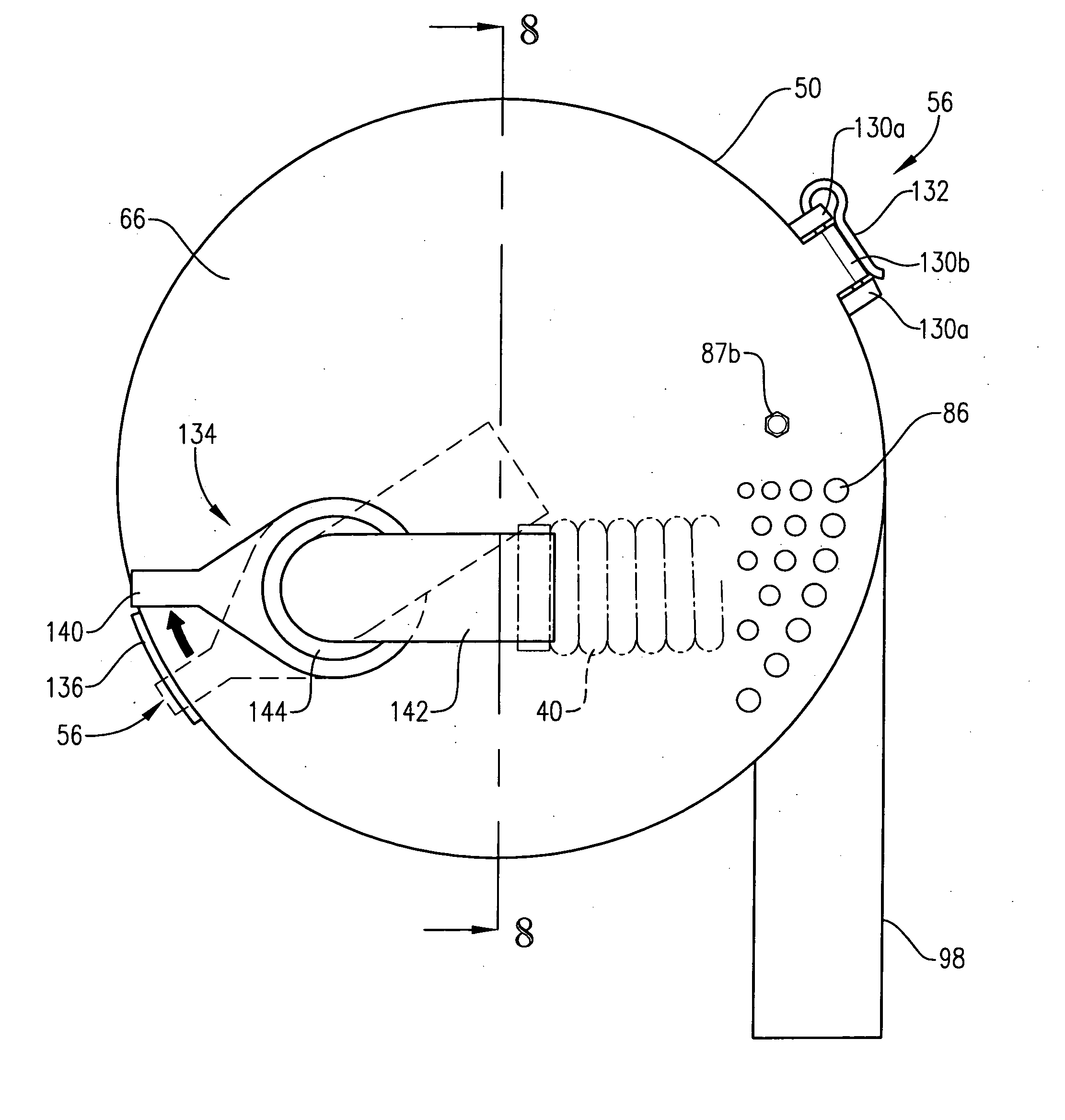
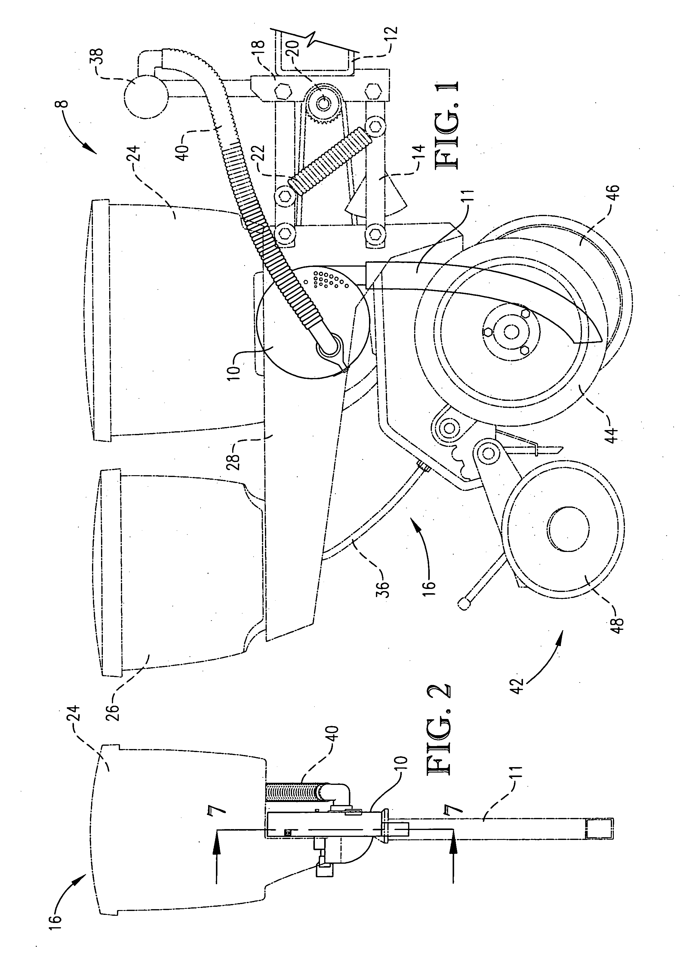
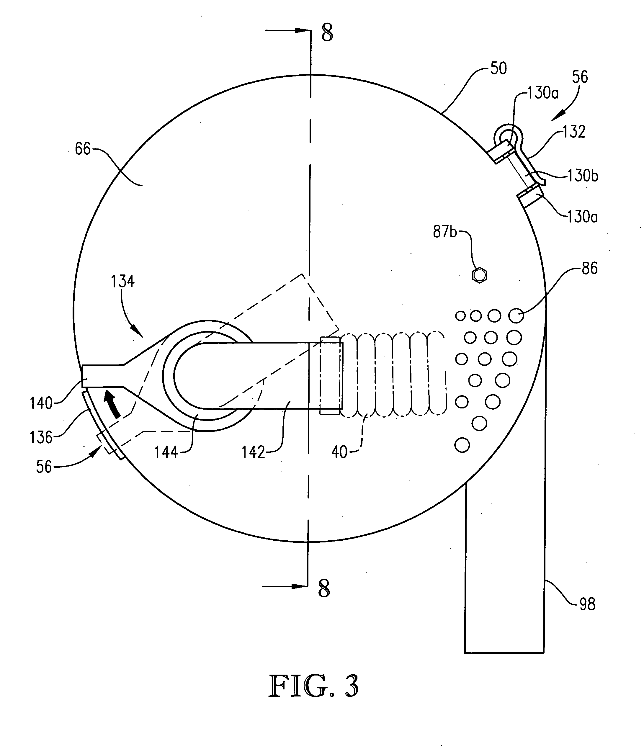
[0031] Referring initially to FIGS. 1 and 2, the present invention concerns a vacuum planter 8 equipped with an improved vacuum seed meter 10 for continuously planting single agricultural seeds (e.g., cotton, soybeans, and corn) at a predetermined rate. The improved seed meter 10 is attached to a rear frame 14 of a mobile support structure 12 of the planter 8. The frame 14 is provided for supporting and manipulating a plurality of planting assemblies 16 and includes a mount 18 for connecting the frame 14 to the mobile support structure 12. The frame 14 includes a linear actuator 22 for vertically shifting the frame 14 relative the mobile carrier 12 between a lower engaged position and a raised transportation position. A drive mechanism 20 can also be coupled to the frame 14. The drive mechanism 20 can be configured to transfer the rotation of the wheels (not shown) of the planter 8 to the seed meter 10. Alternatively, the drive mechanism 20 can be electrically or hydraulically drive...


PUM


Abstract

A vacuum seed meter for metering individual seeds at consistent intervals. The seed meter employs an improved seed disk defining a plurality of seed attachment holes for holding seeds on the disk via a vacuum attachment force. Each seed attachment hole is configured to allow a seed to be held against one side of the disk without permitting the seed to extend entirely through the attachment hole and protrude from the opposite side of the disk. In addition, the seed disk is configured to provide enhanced resistance to bending. No gaskets or brushes that maintain contact with the seed disk are required. The seed meter also employs an improved second-seed eliminator disposed alongside the seed disk. The second-seed eliminator presents a substantially smooth leading edge that is configured to contact a second seed held by an attachment hole, thereby decoupling the second seed from the disk. The second-seed eliminator can be shifted via contact with a seed firmly attached to the seed disk, thereby preventing shearing of the seed by the seed eliminator.

Description

BACKGROUND OF THE INVENTION [0001] 1. Field of the Invention [0002] The present invention relates generally to agricultural seed planting devices. In another aspect, the invention concerns an improved seed meter for metering individual seeds at consistent intervals. [0003] 2. Discussion of Prior Art [0004] A variety of configurations of agricultural planters are available on the market today. One popular type of planter is known as a vacuum or air planter. A typical vacuum planter can be used to simultaneously plant 8 to 16 (typically 12) rows of seed. Vacuum planters include one negative air-pressure (i.e., vacuum) seed meter for each row planted. These vacuum seed meters are configured to discharge individual seeds at consistent intervals. [0005] Conventional vacuum seed meters include a housing attached to a vacuum source and a seed disk disposed in and rotatable relative to the housing. The seed disk defines a plurality of symmetric seed attachment holes where individual seeds a...

Claims


Application Information

Patent Timeline
IPC IPC(8): A01C7/04
CPCA01C7/046A01C7/0443
Inventor FRIESEN, ENRIQUE
Owner FRIESEN ENRIQUE
Learn More