Methods and materials for reducing damage from environmental electromagnetic effects
Inactive Publication Date: 2005-07-14
INTEGUMENT TECH
View PDF31 Cites 50 Cited by
Summary
Abstract
Description
Claims
Application Information
AI Technical Summary
This helps you quickly interpret patents by identifying the three key elements:
Problems solved by technology
Method used
Benefits of technology
Benefits of technology
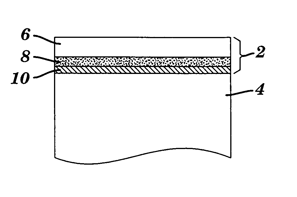
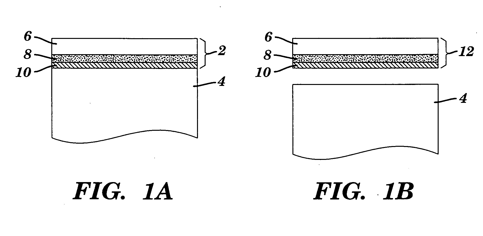
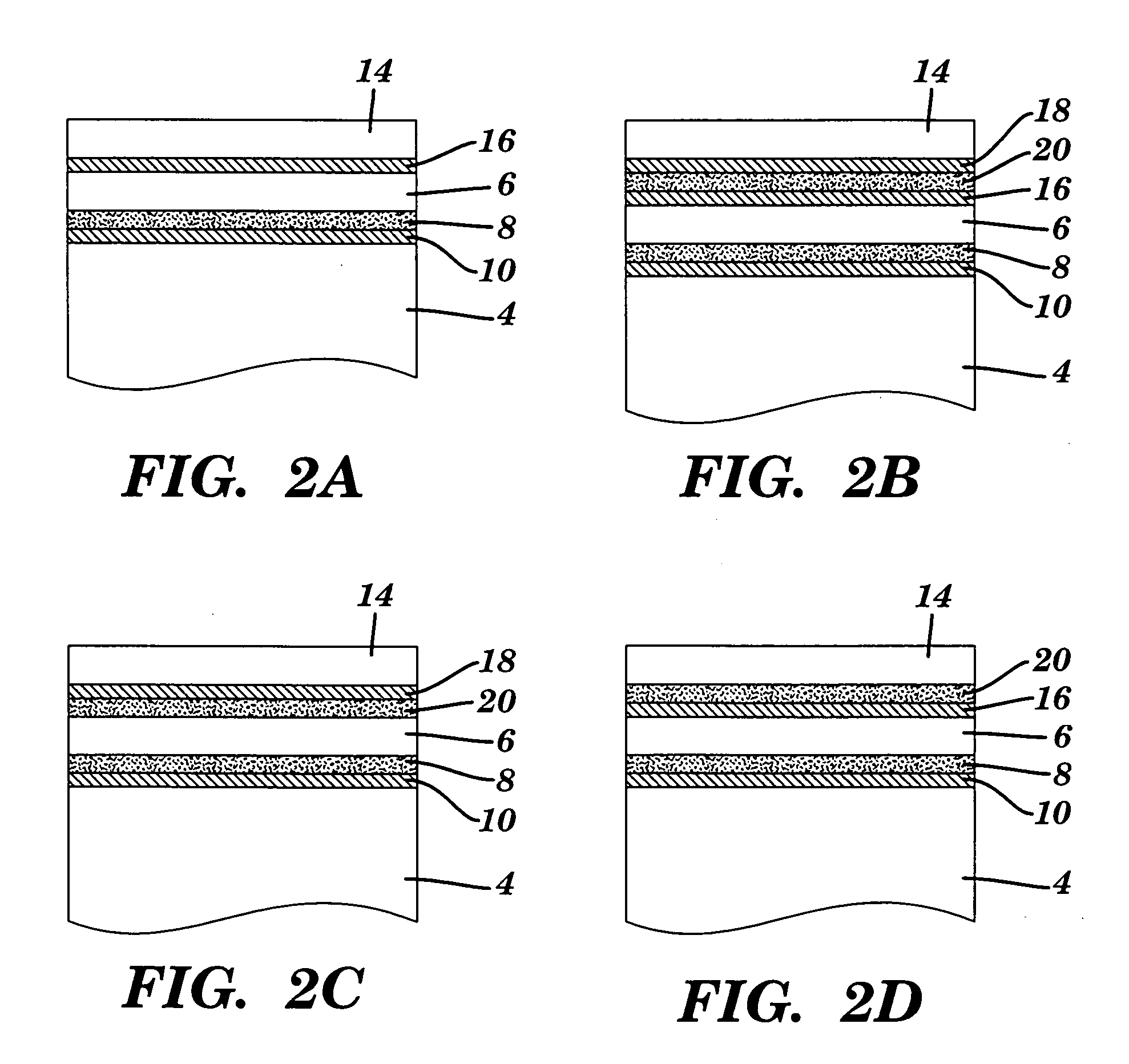
[0007] The present invention relates to a method of reducing damage resulting from environmental electromagnetic effects on a non-metallic surface. The method inclu
Problems solved by technology
A variety of objects, particularly, objects having non-metallic surfaces, can be prone to environmental electromagnetic effects, such as lightning strikes.
Once such penetration occurs further damage can be done as the lightning pathway “intrudes” on the avionics, power supply circuitry, or other critical systems, and actual physical damage may result as this current surge travels around and through the inside of the aircraft.
Electromagnetic fields that
Method used
Image
Click on the blue label to locate the original text in one second.
Reading with bidirectional positioning of images and text.
Examples
example 1
Lightning Strike Tests: Materials and Methods
[0089] This example sets forth the codes that are used in Examples 2-6.
[0090]“PVDF” is polyvinylidene fluoride (also known as HYLAR™). “5PVDFCU” is 5 mil PVDF with 4 mil acrylic (Adchem 747) adhesive, Astroseal Cu expanded copper foil (Part No. CU 029 CXM C26), and 4 mil acrylic adhesive (Adchem 747). “2PVDFCU” is 2 mil PVDF with 4 mil acrylic (Adchem 747) adhesive, Astroseal Cu expanded copper foil (Part No. CU 029 CXM C26), and 4 mil acrylic adhesive (Adchem 747).
[0091]“MFA” is perfluoroalkoxy fluoropolymer known as HYFLON™. “5MFACU” is 5 mil MFA with 4 mil acrylic (Adchem 747) adhesive, Astroseal Cu expanded copper foil (Part No. CU 029 CXM C26), and 4 mil acrylic adhesive (Adchem 747). “2MFACU” is 2 mil MFA with 4 mil acrylic (Adchem 747) adhesive, Astroseal Cu expanded copper foil (Part No. CU 029 CXM C26), and 4 mil acrylic adhesive (Adchem 747). “5MFA” is 5 mil MFA with 4 mil acrylic (Adchem 747) adhesive. “2MFA” is 2 mil MFA wi...
example 2
Lightning Strike Tests: Test Panels
[0093] Nine carbon composite test panels were laminated with polymer film appliques using a different permutation for each panel. More particularly, Test Panels 1-9 were constructed as follows: [0094] 1. 5PVDFCU [0095] 2. 2PVDFCU [0096] 3. 5PVDF over Cu metallized MFA fabric [0097] 4. 2PVDF over Cu metallized MFA fabric [0098] 5. 5PVDFCU over Cu metallized MFA fabric [0099] 6. 2PVFCU [0100] 7. 2MFACU [0101] 8. 5MFACU [0102] 9. 5MFACU over Cu metallized MFA fabric
In each of test Panels 3-5 and 9, the fabric material was laminated under the 5PVDF, 2PVDF, 5PVDFCU, or 5MFACU such that the fabric was directly laminated onto the carbon composite with the 5PVDF, 2PVDF, 5PVDFCU, or 5MFACU laminated over the MFA metallized fabric.
example 3
Lightning Strike Tests: Test Procedures
[0103] Test panels were tested at Lightning Technologies, Inc. in Pittsfield, Mass. The tests were designed to demonstrate various levels of lightning strike protection capabilities of each tested applique. Each lightning strike applique material showed different levels of lightning strike protection as described below in Tables 3 and 4. Additionally, Tables 3 and 4 list various levels of utility for actual lightning strike protection including a 106 volt dielectric breakdown high voltage test and a Zone 2A high current test including components B, C, and D. All calibrations were performed in accordance with MIL-STD-45662A
[0104] For the high voltage tests, each panel to be tested was positioned horizontally on supports directly beneath a 10 cm diameter spherical electrode connected to the output of a high voltage generator. The air gap between the electrode and the panel surface was set at 0.5 m or 1 m,. All conductive elements were grounded....
PUM
Property
Measurement
Unit
Metallic bond
aaaaa
aaaaa
Electromagnetism
aaaaa
aaaaa
Abstract
Disclosed is a method of reducing damage resulting from environmental electromagnetic effects on a non-metallic surface. The method includes disposing a polymeric sheet material over the non-metallic surface and disposing a metal layer between the non-metallic surface and the polymeric sheet material. Objects which includes a substrate having a non-metallic surface, a halopolymer sheet material disposed over the substrate's non-metallic surface, and a metal layer disposed between the halopolymer sheet material and the substrate's non-metallic surface are also described. Laminates are also disclosed. One such laminate includes a metal layer having a first surface and a second surface, a halopolymer sheet material bonded or adhered to the first surface of the metal layer, and an adhesive disposed on the second surface of the metal layer. Another such laminate includes a halopolymer fabric having a first surface and a second surface, a metal layer bonded or adhered to the first surface of the halopolymer fabric, and an adhesive disposed on the second surface of the halopolymer fabric.
Description
[0001] The present invention claims the benefit of U.S. Provisional Patent Application Ser. No. 60 / 234,424, filed Sep. 21, 2000, which is hereby incorporated by reference.FIELD OF THE INVENTION [0002] The subject invention relates, generally, to methods and materials for reducing damage resulting from environmental electromagnetic effects and, more particularly, to a methods and materials for reducing damage resulting from lightning strikes. BACKGROUND OF THE INVENTION [0003] A variety of objects, particularly, objects having non-metallic surfaces, can be prone to environmental electromagnetic effects, such as lightning strikes. For example, MIL-STD-464 describes the importance of considering environmental electromagnetic effects (“E3”) when selecting materials for use in military aircraft. More particularly, MIL-STD-464 specifies that all systems, subsystems, and equipment used in constructing an aircraft should be compatible with internal electromagnetic emissions (e.g., electroni...
Claims
Application Information
Patent Timeline
Application Date:The date an application was filed.
Publication Date:The date a patent or application was officially published.
First Publication Date:The earliest publication date of a patent with the same application number.
Issue Date:Publication date of the patent grant document.
PCT Entry Date:The Entry date of PCT National Phase.
Estimated Expiry Date:The statutory expiry date of a patent right according to the Patent Law, and it is the longest term of protection that the patent right can achieve without the termination of the patent right due to other reasons(Term extension factor has been taken into account ).
Invalid Date:Actual expiry date is based on effective date or publication date of legal transaction data of invalid patent.

