Deployable, rigidizable wing

a technology of wing and wing body, applied in the direction of aircraft, wing shape, transportation and packaging, etc., can solve the problems of not being rigid, not being able to bear a portion of structural load, not being supported, etc., to achieve favorable aerodynamic characteristics, increase the rigidity, and the effect of increasing the aspect ratio

Inactive Publication Date: 2005-07-14
ILC DOVER LP
View PDF15 Cites 43 Cited by
  • Summary
  • Abstract
  • Description
  • Claims
  • Application Information

AI Technical Summary

Benefits of technology

[0016] Many advantages are realized in an inflatable, rigidizable wing, the most notable of which is an increase in stiffness compared to a conventional inflatable wing. This improvement is potentially on the order of several orders of magnitude. This allows the potential to construct thinner, higher aspect ratio wings than has been possible using conventional inflatable wing approaches. A thinner, higher aspect ratio wing possesses favorable aerodynamic characteristics, the most significant of which is lower drag, hence improved fuel economy and lift to drag ratio. A further advantage is that by elim

Problems solved by technology

The covering may or may not be rigidizable, may or may not bear a portion of the structural

Method used


Image

  • Deployable, rigidizable wing
  • Deployable, rigidizable wing
  • Deployable, rigidizable wing

Examples


Embodiment Construction

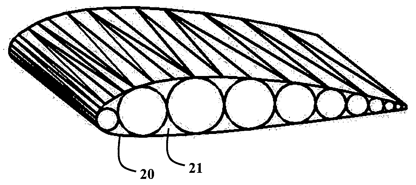
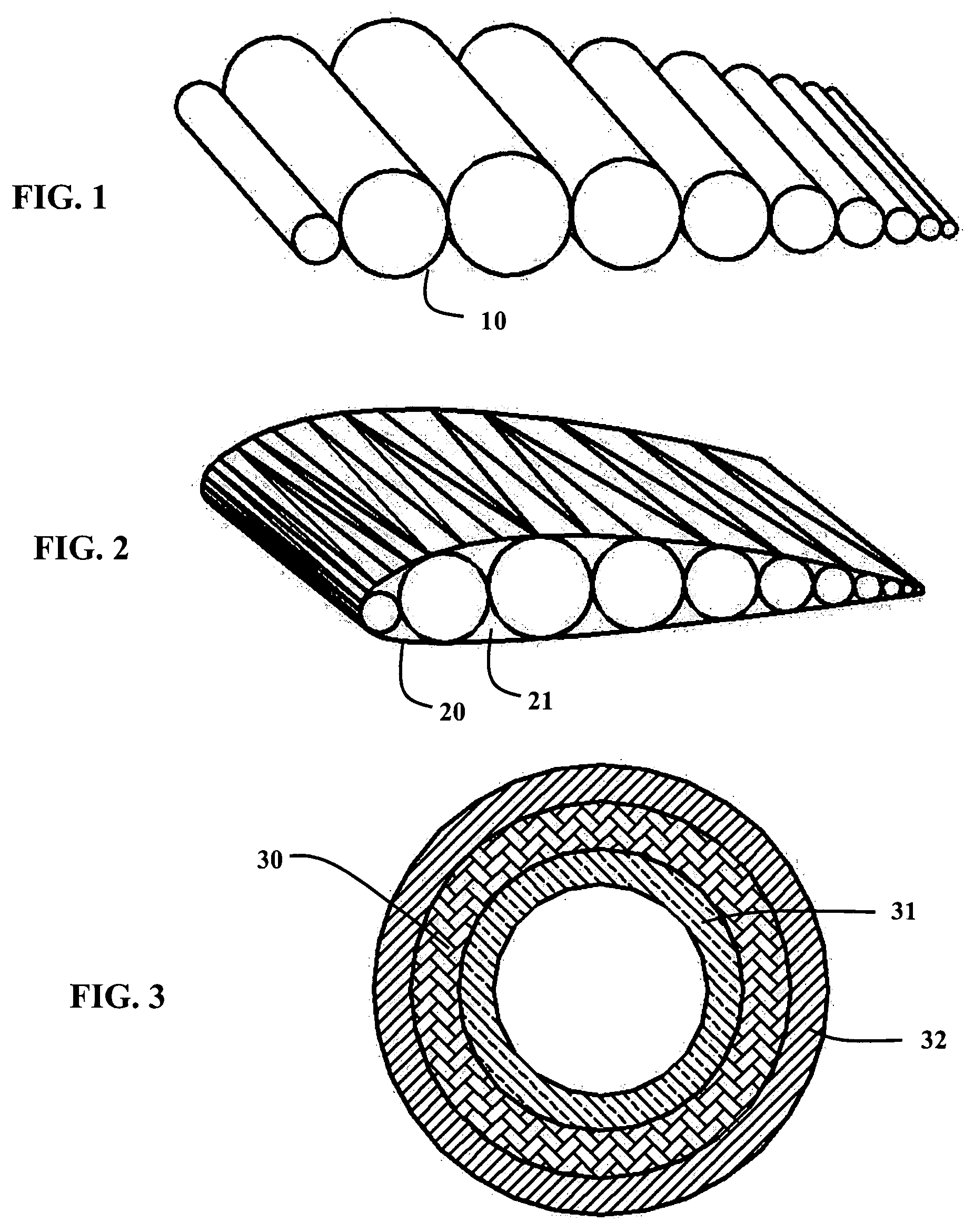
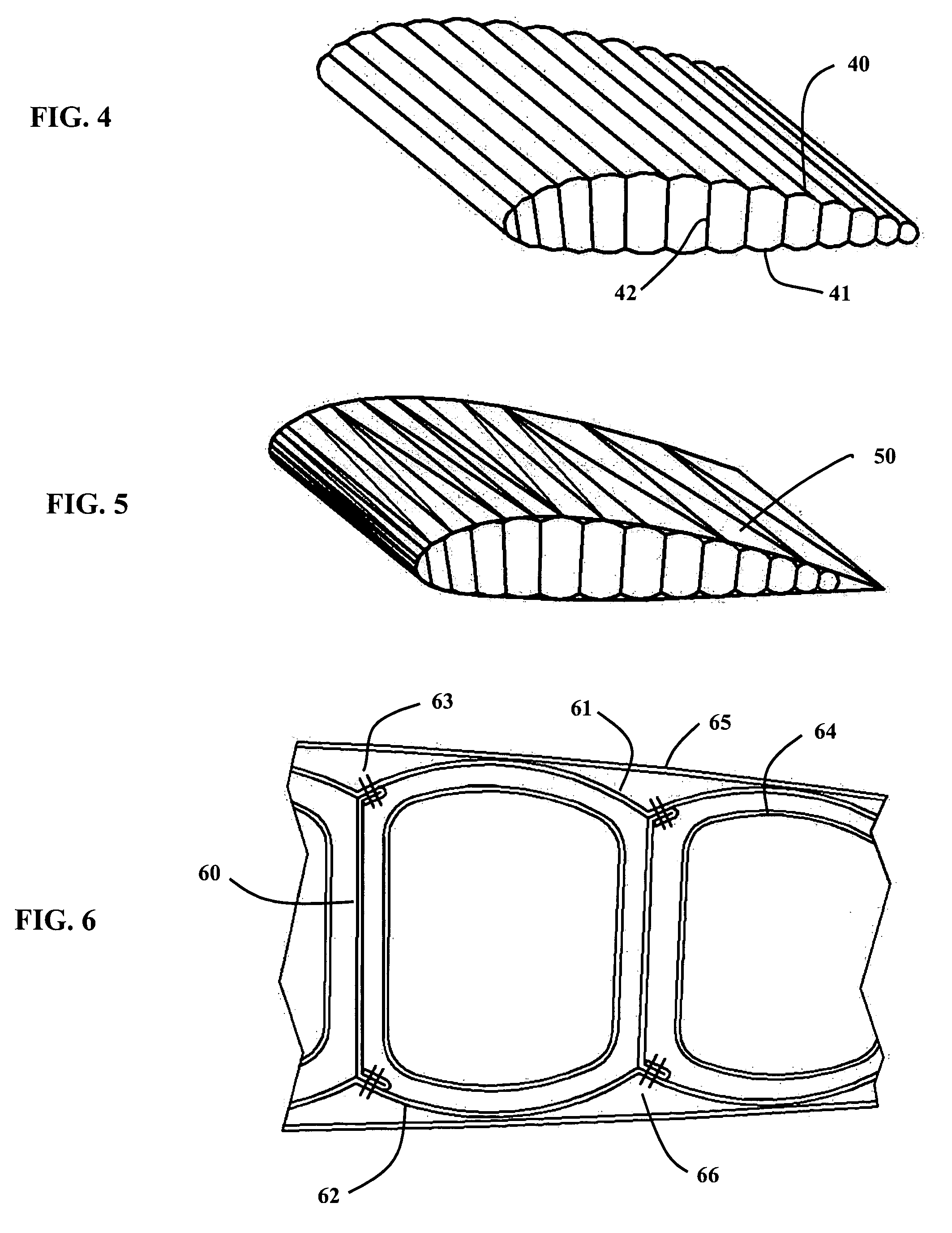
[0025] Three embodiments of inflatable / expandable, rigidizable wings are described below. For purposes of the description, the rigidizing technique described is based on an light cure (photo-initiation) rigidization mechanism. It is understood that this is but one of several cure mechanisms upon which the rigidization process can be based. For example, any type of light capable photo-initiating rigidization process, i.e., ultraviolet, visible and infrared light, can be used, or the gas used to expand may be, or may contain a curing agent to rigidify the wing. Such curing agent-containing gas may also be introduced to the wing after it has been fully expanded. Further, the means of deployment described is based upon the use of an inflation gas. However, it is understood that other means of deployment could be used, such as mechanical linkages, shape memory materials, and so forth.

[0026] As used throughout the specification and claims, the term “self supporting” means without the nee...


PUM


Abstract

A novel design and construction method for an inflatable, rigidizable wing for a terrestrial or planetary flying vehicle. The wing is caused to deploy from an initially packed condition and to assume its functional shape by means of an inflation gas. After inflation, the wing is rigidized by any of several means, such that the inflation gas is no longer required. The composite wing is fabricated from a base reinforcement material, often a fabric, which is coated with a polymer resin that hardens when exposed to a curing mechanism. Several activation mechanisms exist by which to initiate rigidization of such a structure, including elevated temperature, ultraviolet light, and chemical constituents of the inflation gas. The resultant wing has fundamental advantages compared to existing inflatable wings, including improved stiffness, and reduced susceptibility to structural failure in response to puncture.

Description

[0001] This application is a non-provisional application of U.S. Provisional Application No. 60 / 444,665, filed Feb. 4, 2003, incorporated by reference in its entirety (including all of the references discussed therein).BACKGROUND OF THE INVENTION [0002] 1. Field of the Invention [0003] The present invention relates to the field of expandable structures which can be subsequently rigidized to be self supporting and finds utility in aircraft components, specifically wings, which can be inflated and rigidized to prevent deformation thereof. [0004] 2. Background [0005] Inflatable wings have been in existence for decades and have found application in a variety of manned and unmanned aircraft, and as control surfaces for munitions and Lighter Than Air (LTA) vehicles such as aerostats. Recent technological advances, in the context of a society that is increasingly risk averse, have resulted in increased interest in the use of Unmanned Aerial Vehicles (UAVs). Many of the vehicles under devel...

Claims


Application Information

Patent Timeline
IPC IPC(8): B64CB64C3/00B64C3/56B64C39/02
CPCB64C3/56B64C2201/105B64C39/024B64U30/12
Inventor CADOGAN, DAVID P.GRAZIOSI, DAVID ALLENLEE, GRANT RYANSCARBOROUGH, STEPHEN EMERSONSMITH, TIMOTHY R.
Owner ILC DOVER LP
Why Eureka
Try Eureka