
Spring washer

a technology of spring washer and washer body, which is applied in the field of spring washer, can solve the problems of affecting the service life of the spring washer, and consuming a large amount of force per level of deflection, so as to achieve the effect of long service life, easy field use, and high spring ra

Inactive Publication Date: 2005-07-14
BARNES GROUP
View PDF12 Cites 49 Cited by
  • Summary
  • Abstract
  • Description
  • Claims
  • Application Information

AI Technical Summary

Benefits of technology

[0011] A spring washer according to one aspect of the present invention can utilize spring fingers which extend at different angles to produce a wider range of axial loads.
[0019] Another object is the provision of a spring washer of the foregoing character which provides easier adjustment to the produced axial load.
[0022] A further object is the provision of a spring washer of the foregoing character which is economical to manufacture, easy to use in the field, and has a long service life.

Problems solved by technology

However, the spring rate of a prior art Belleville-style washer is very high due to its conical configuration.
Deflection of the cone shape takes a significant amount of force per the level of deflection.
Furthermore, Belleville-style washers known in the art produce forces which change exponentially per unit of deflection.
Therefore, they produce / high axial load per unit of deflection (high spring rate) and are increasingly difficult to adjust to a desired axial load as they are compressed.
While high axial loads can be used for some applications, producing a desired axial load can be difficult.
Another disadvantage with Belleville-style washers is the limited range of deflection which can be used for producing a controllable and repeatable axial load.
This condition is due to the conical configuration and the resulting high stresses produced after only a limited amount of deflection.
Slotted spring washers are also conical and have a limited range of motion.
However, a slotted spring washer provides only a very light load which is a function of the geometry of the slots and the configuration of the ring connecting the fingers.
As can be appreciated, the need to manipulate a washer to distinguish the top and the bottom of the washer can be very difficult and costly in both manual assembly operations and in automated assembly operations.

Method used


Image

  • Spring washer
  • Spring washer
  • Spring washer

Examples


Embodiment Construction

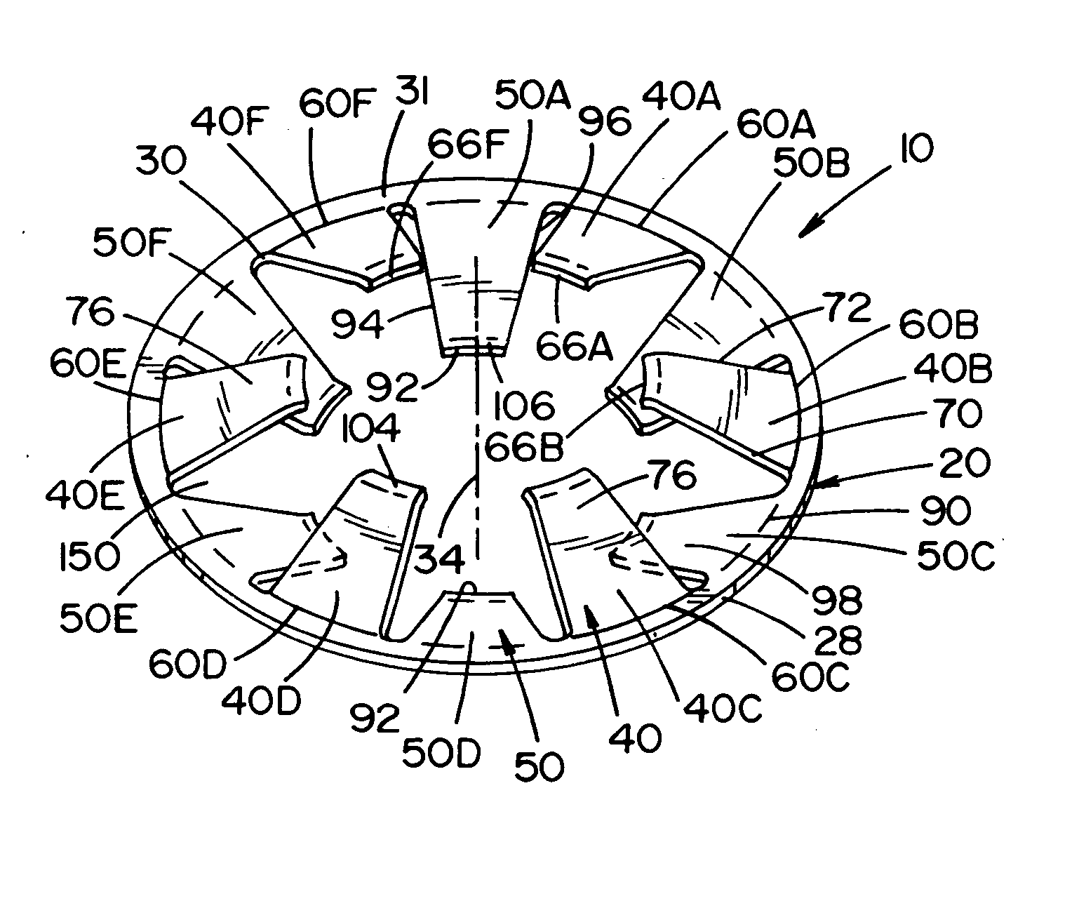
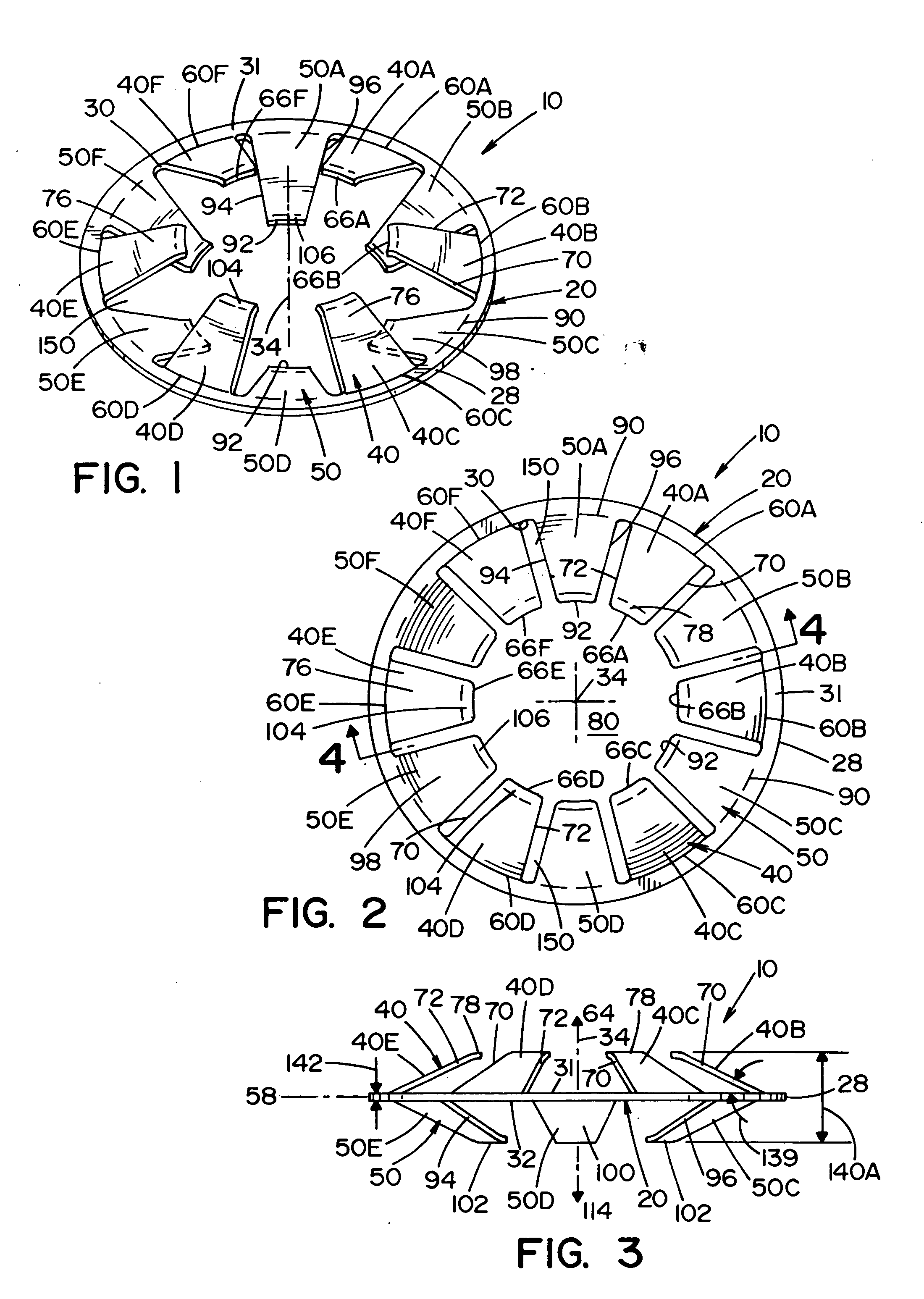
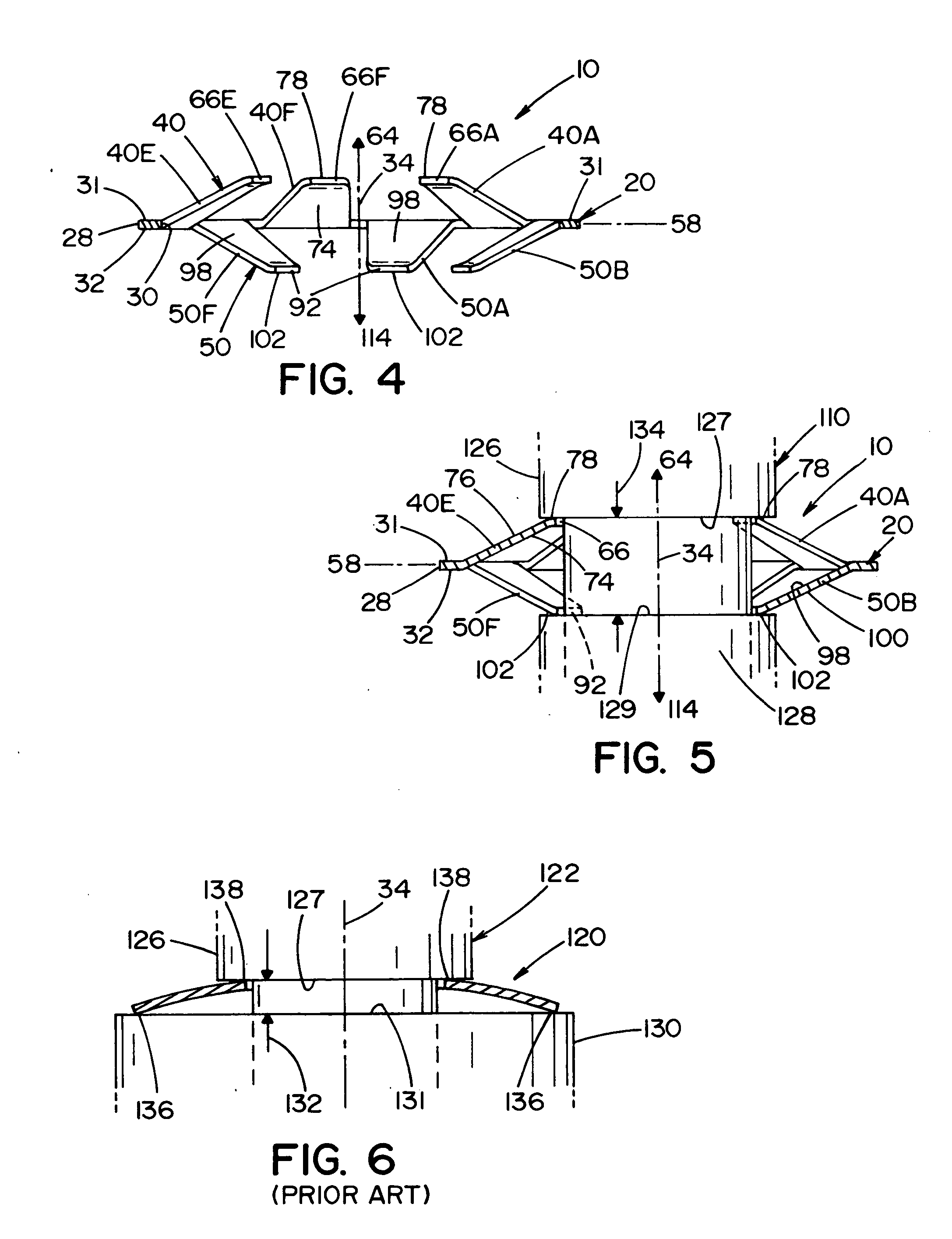
[0038] Referring now in greater detail to the drawing wherein the showings are for the purpose of illustrating preferred embodiments of the invention only, and not for the purpose of limiting the invention, FIGS. 1-5 illustrate a spring washer 10 having an outer body 20 which has an outer peripheral edge 28, an inner edge 30, a top surface 31 and a bottom surface 32. Outer body 20 extends about a central washer axis 34 and is shown in this embodiment to be an annular body. Central axis 34 defines an axial direction which is perpendicular to a washer plane 58 that is defined by outer washer body 20. Washer 10 further includes a first set of inwardly extending fingers 40 and a second set of inwardly extending fingers 50. First set of fingers 40 are shown to include six fingers 40A-40F and, similarly, second set of fingers 50 are shown to have six fingers 50A-50F. However, first and second set of fingers 40 and 50 can include more or less than six fingers without detracting from the in...


PUM


Abstract

A spring washer for producing a load in an axial direction which includes an outer spring body extending about a central washer axis parallel to the axial direction. The washer further includes a central opening coaxial to the washer axis for accepting at least a portion of an elongated object extending in the axial direction. The washer has a plurality of circumferentially spaced spring fingers each extending inwardly towards the central washer opening. Each finger including a finger base attached to the outer body and a finger end adjacent to the central opening. The finger end of every other one of the plurality of spring fingers being axially spaced on either side of said outer spring body.

Description

[0001] This invention relates to the art of spring washers and, more particularly, to a slotted spring washer for applying axial loads. INCORPORATION BY REFERENCE [0002] The present invention relates to spring washers which are capable of producing an axial load. Knocke U.S. Pat. No. 3,009,176 discloses a Belleville spring washer utilized in a bolt assembly and is incorporated by reference for showing the same. Schober U.S. Pat. No. 4,039,354 discloses a method of making a Belleville spring and is incorporated by reference herein for the same. Labesky U.S. Pat. No. 6,102,382 discloses a Belleville spring and is incorporated by reference herein as background material for showing the same. Johnson U.S. Pat. No. 3,259,383 discloses a slotted spring washer and is incorporated by reference herein for showing the same. BACKGROUND OF THE INVENTION [0003] It is, of course, well known that a washer can be used to produce an axial load. Further, it is well known that a Belleville or a slotted...

Claims


Application Information

Patent Timeline
IPC IPC(8): F16F1/20F16F1/32F16F1/34
CPCF16F1/32
Inventor RODEFFER, MARK A.
Owner BARNES GROUP
Learn More