
Motorcycle steering damper

Inactive Publication Date: 2005-07-14
YAMAHA MOTOR CO LTD
View PDF8 Cites 27 Cited by
  • Summary
  • Abstract
  • Description
  • Claims
  • Application Information

AI Technical Summary

Benefits of technology

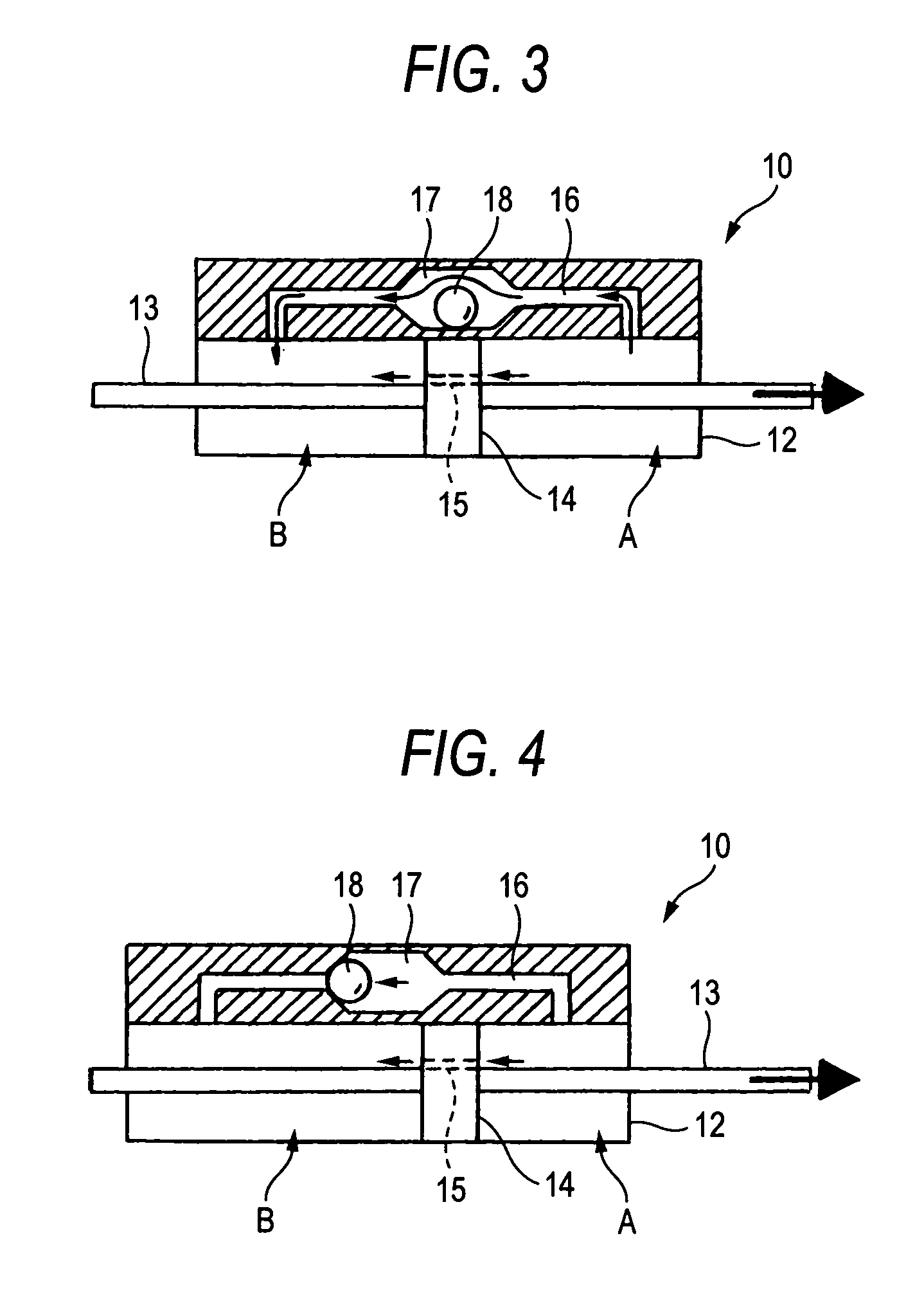
[0013] Consequently, according to the first to third aspects of the invention, since a mechanical construction is adopted in which, when the steering speed exceeds the normal range, whereby the differential pressure between the two oil chambers in the cylinder reaches or exceeds the certain value, the check ball is moved by virtue of the differential pressure to thereby reduce the cross-sectional area of the passageway, the necessity of a sensor or electrical control is obviated, so that the occurrence of vibrations at the front wheel system due to disturbance can be suppressed while attempting to reduce the production costs by decreasing the number of components involved and to secure high reliability which results from the entrainment of no delay in control.

Problems solved by technology

In the event that a large disturbance is imparted to the front wheel system from a road surface in such a condition, the vibration of the front wheel system increases, thereby damaging the driving stability.
However, since the conventional steering damper needs sensors for detecting the vehicle speed and steering angle, so that the electromagnetic valve and the like are controlled to operate based on detection signals from the sensors, there are caused problems that the number of components is increased to thereby call for an increase in costs and that highly reliable operations are difficult to be secured due to a delay in control.

Method used


Image

  • Motorcycle steering damper
  • Motorcycle steering damper
  • Motorcycle steering damper

Examples


Embodiment Construction

[0027] Embodiments of the invention will be described below based on the accompanying drawings.

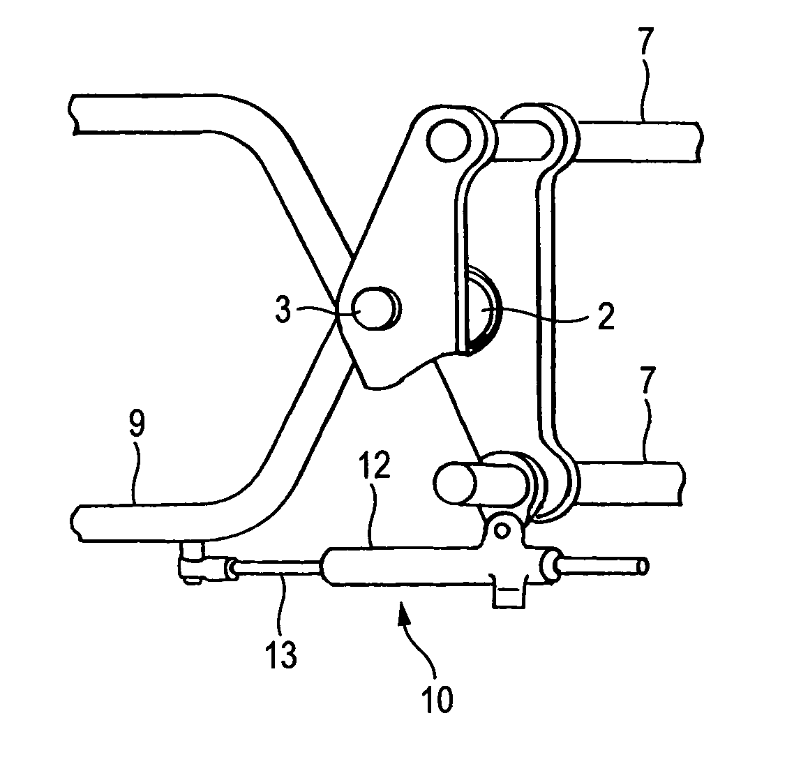
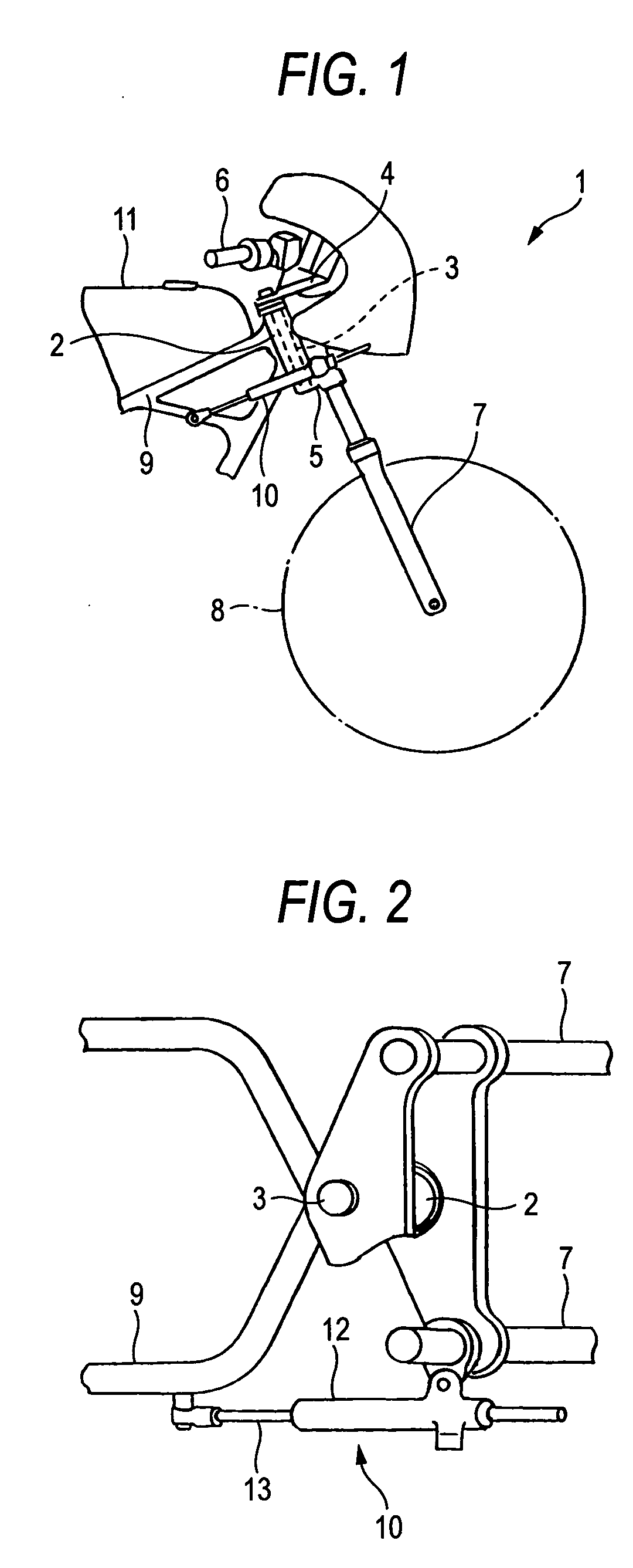
[0028]FIG. 1 is a right side view of a front part of a motorcycle provided with a steering damper according to the invention, and FIG. 2 is a plan view of the front part of the motorcycle illustrating a construction in which the steering damper is arranged.

[0029] In a motorcycle 1 shown in FIG. 1, reference numeral 2 denotes a head pipe located at an upper portion of the front of a vehicle body, and a steering shaft 3 is passed through and supported rotatably in the head pipe 2 and an upper bracket 4 and a lower bracket 5 are attached to the steering shaft 3 at upper and lower ends thereof, respectively. Then, a handlebar 6 is attached to the upper bracket 4 and an upper portion of a front fork 7 is passed and supported between the upper bracket 4 and the lower bracket 5, a front wheel 8 being rotationally supported at a lower portion of the front fork 7.

[0030] In addition, a vehicle bo...


PUM


Abstract

According to the invention, there is provided a steering damper (10) in which the interior of a cylinder (12) is divided into two oil chambers (A), (B) by a piston (14) which slides in the cylinder (12) as a steering operation takes place, an oil hole (15) is formed in the piston (14) for providing a communication between the two oil chambers (A), (B) and a bypass passageway (16) is provided for allowing oil in one (A or B) of the oil chambers to flow into the other oil chamber (B or A) by bypassing the oil hole (15), the motorcycle steering damper being characterized in that a subsidiary chamber (17) is defined at an intermediate position along the length of the bypass passageway (16), and in that a check ball (18) is provided in the subsidiary chamber (17), the check ball is adapted to move so as to close the bypass passageway (16) when a steering speed exceeds a predetermined value and a differential pressure between the two oil chambers reaches or exceeds a certain value. Consequently, according to the invention, the mechanical operation of the motorcycle steering damper (10) can be ensured without needing an electrical control, and the vibration of a front wheel system due to disturbance can be suppressed while attempting to reduce the production costs by decreasing the number of components involved and to secure high reliability.

Description

TECHNICAL FIELD [0001] The present invention relates to a motorcycle steering damper for suppressing vibrations at a front wheel system due to disturbance. BACKGROUND ART [0002] When the motorcycle is running at high speed, the grounding load at a front wheel system of a motorcycle decreases due to lift. In the event that a large disturbance is imparted to the front wheel system from a road surface in such a condition, the vibration of the front wheel system increases, thereby damaging the driving stability. [0003] Then, there is provided a proposal in which a steering damper is provided between a steering system member such as a steering bracket and a vehicle body frame for absorbing disturbance from the road surface by virtue of a damping force generated on the steering damper so provided to thereby suppress the vibration of the front wheel system (for example, refer to JP-A-2000-301680). [0004] The steering damper is constructed such that the interior of a cylinder is divided int...

Claims


Application Information

Patent Timeline
IPC IPC(8): B62K21/08F16F9/19F16F9/34F16F9/50F16F9/512
CPCB62K21/08F16F9/512F16F9/19Y10T137/7873Y10T137/778
Inventor IWAMOTO, TADAMITSUFUJIMORI, TAKAFUMI
Owner YAMAHA MOTOR CO LTD
Learn More