Electric motor assembly with a module attached to a motor housing

a technology of electric motors and modules, applied in the direction of supports/enclosements/casings, dynamo-electric components, mechanical energy handling, etc., can solve the problems of assembly and adjustment of governors and switches, and achieve the effect of eliminating the possibility of being damaged by anything and being easy to attach

Inactive Publication Date: 2005-07-14
A O SMITH
View PDF16 Cites 0 Cited by
  • Summary
  • Abstract
  • Description
  • Claims
  • Application Information

AI Technical Summary

Benefits of technology

[0005] Another of the principal objects of the invention is to provide an electric motor with a governor and a switch where the module can be easily attached to the motor housing.
[0006] Another of the principal objects of the invention is to provide an electric motor with a governor and a switch where the switch and the governor are totally enclosed, eliminating the possibility of being damaged by anything inside the motor housing.
[0007] More particularly, this invention provides an electric motor assembly including a mechanism for mounting a module housing end on a motor housing end, and a mechanism for drivingly connecting a module shaft end to a motor shaft end. The assembly further includes a mechanism for preventing the module housing from rotating relative to the motor housing, and a mechanism for slidably attaching for shaft axis direction movement relative to each other the module housing and the motor housing. The module shaft end and the motor shaft end are located relative to their respective housings so that they can be drivingly connected to each other without the module housing and the motor housing interfering with the connection.

Problems solved by technology

Extensive labor is required for assembly and adjusting the governor and switch.

Method used


Image

  • Electric motor assembly with a module attached to a motor housing
  • Electric motor assembly with a module attached to a motor housing
  • Electric motor assembly with a module attached to a motor housing

Examples


Embodiment Construction

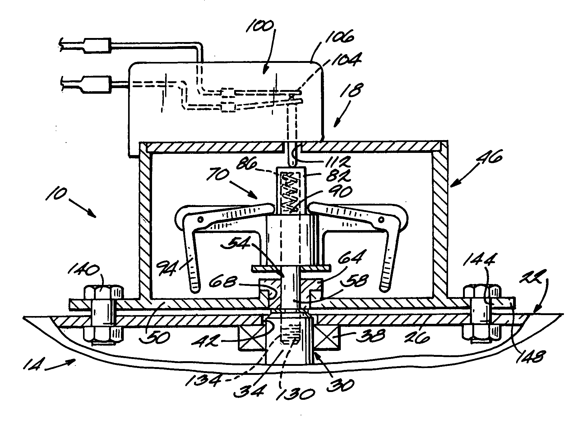
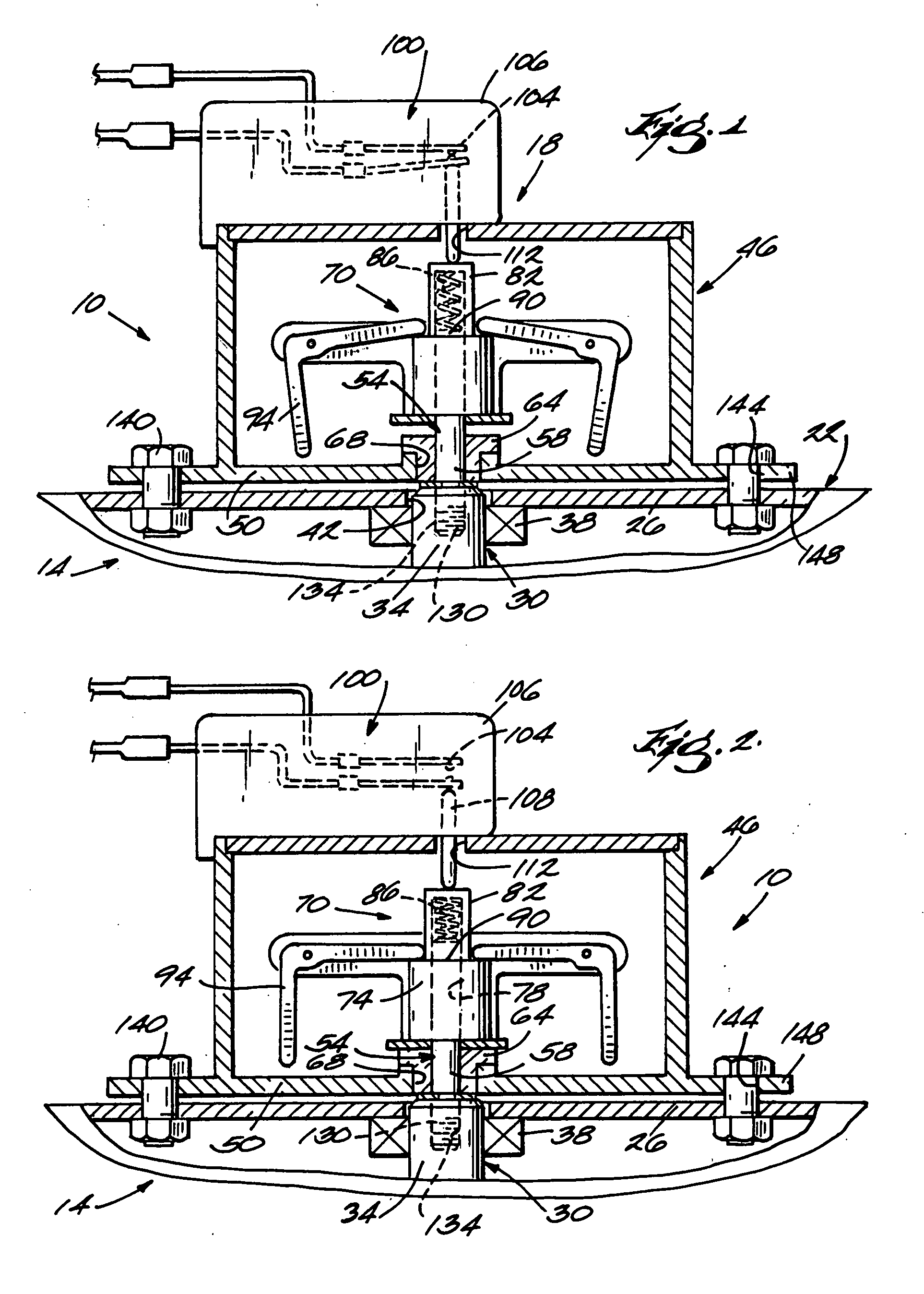
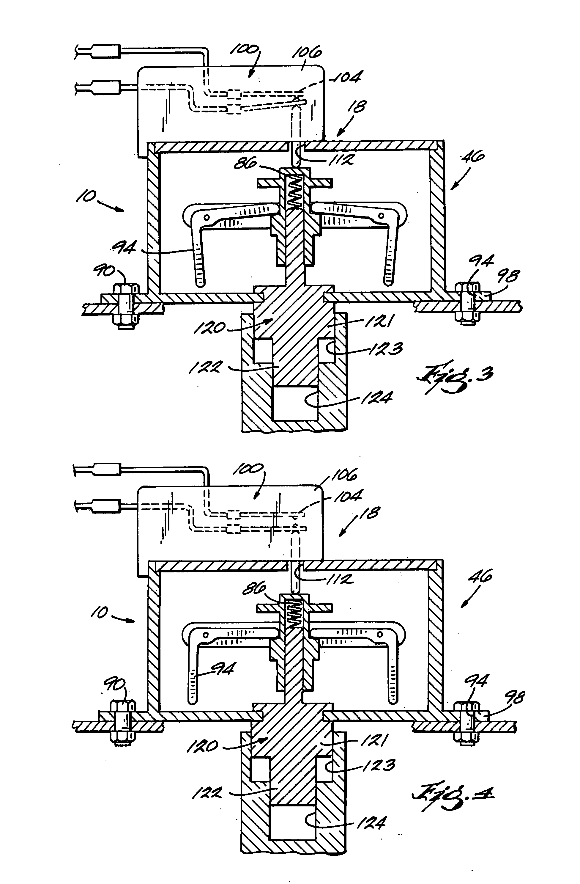
[0013] As illustrated in FIGS. 1 through 4, and especially FIGS. 1 and 2, the invention comprises an electric motor assembly 10 including an electric motor 14 and a module 18. The electric motor 14 includes a motor housing 22 having an end 26, and a motor shaft 30 having an end 34 adjacent the motor housing end 26. The electric motor 14 further includes means in the form of bearings 38 in the motor housing 22 for rotatably mounting the motor shaft 30 in the motor housing 22. In other embodiments, other means for mounting the motor shaft 30 in the motor housing 22 can be used. The orientation of the motor shaft 30 defines a motor shaft axis direction. The electric motor 14 also includes an opening 42 in the motor housing 22. The opening 42 provides access from outside of the motor 14 to the motor shaft end 34.

[0014] The module 18 includes a module housing 46 having an end 50, and a module shaft 54 having an end 58 adjacent the module housing end 50. The module 18 further includes me...


PUM

PropertyMeasurementUnit
speedaaaaaaaaaa
massaaaaaaaaaa
sizeaaaaaaaaaa

Abstract

An electric motor assembly including a mechanism for mounting a module housing end on a motor housing end, and a mechanism for drivingly connecting a module shaft end to a motor shaft end. The assembly further includes a mechanism for preventing the module housing from rotating relative to the motor housing, and a mechanism for slidably attaching for shaft axis direction movement relative to each other the module housing and the motor housing. The module shaft end and the motor shaft end are located relative to their respective housings so that they can be drivingly connected to each other without the module housing and the motor housing interfering with the connection.

Description

BACKGROUND OF THE INVENTION [0001] This invention relates to electric motors and modules attached to electric motors, and, more particularly, to governor and switch assembly modules used with electric motors. [0002] A conventional induction motor uses a governor and a switch to disengage the starting capacitor or starting phase winding at a pre-selected speed. In a typical two compartment motor design, the governor is mounted on a motor shaft and the switch is mounted to a motor housing or frame. In order to compensate for the large stack-up tolerances of the parts in the motor assembly, and to provide the necessary snap action, both the governor and the switch have fairly large mass and size. Extensive labor is required for assembly and adjusting the governor and switch. SUMMARY OF THE INVENTION [0003] One of the principal objects of the invention is to provide an electric motor with governor and switch where the relative position of the governor and switch is predefined by a preci...

Claims


Application Information

Patent Timeline
Patent Type & Authority Applications(United States)
IPC IPC(8): H02K5/00H02K11/00H02K15/00
CPCY10T29/49009H02K11/0036H02K11/23
Inventor LIN, CHIH MIN
Owner A O SMITH
Why Eureka
Try Eureka