Electro-wetting displays

a technology of display and display panel, applied in the field of electrowetting display panel, can solve the problems of display not being bistable, reducing the contrast ratio of display panel, dye fading,

Active Publication Date: 2005-07-14
E INK CORPORATION
View PDF99 Cites 338 Cited by
  • Summary
  • Abstract
  • Description
  • Claims
  • Application Information

AI Technical Summary

Benefits of technology

[0014] such that, in the absence of an electric field, the first fluid covers a first area of the substrate, but that upon application of an electric field to the first fluid by the at least one electrode, the first fluid moves to a second area smaller than the

Problems solved by technology

This type of display has a number of problems.
The display is not bistable, since the confinement of the oil to the small portion of the pixel only lasts as long as the field is applied.
The visibility of the oil in a small portion of the pixel reduces the contrast ratio of the display.
The use of a dye dissolved in the oil may give rise to l

Method used


Image

  • Electro-wetting displays
  • Electro-wetting displays
  • Electro-wetting displays

Examples


Embodiment Construction

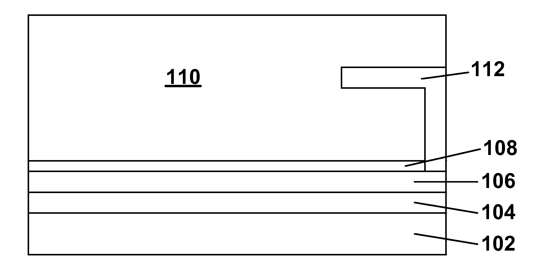
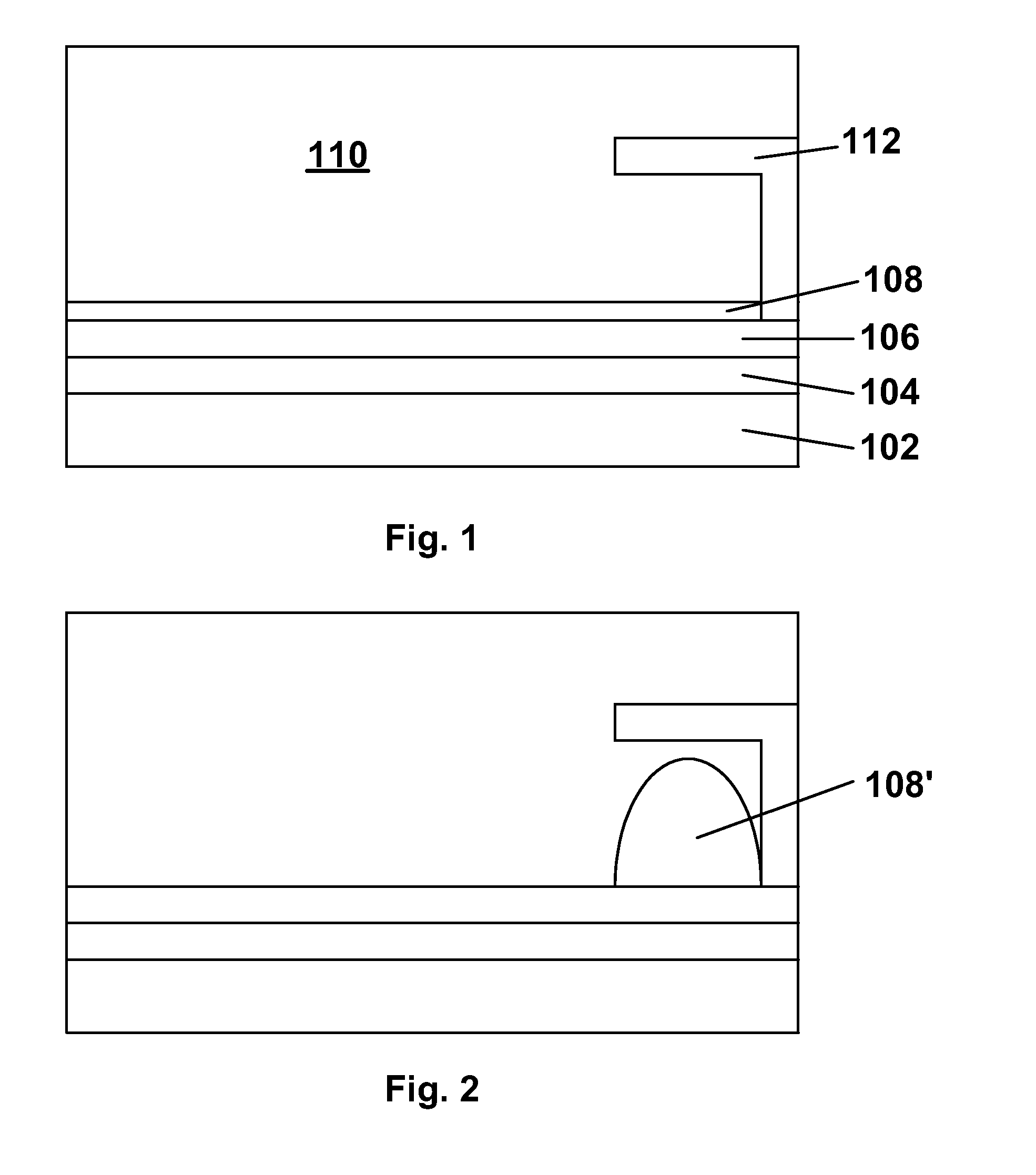
[0061] As already mentioned, this invention has several different aspects. These various aspects will be described separately below, but it should be understood that a single display may make use of multiple aspects of the invention. For example, a microcell display of the invention might use a first fluid colored with pigment particles or nanoparticles in accordance with the pigment / nanoparticle aspect of the invention.

[0062] In the present displays, the first (moving) fluid is typically an oil, while the second fluid is typically aqueous. For ease of comprehension, the description below may use the terms “oil” and “water” instead of first and second fluids, but these terms “oil” and “water” should not be construed in a limitative sense.

[0063] Firstly, as already mentioned, the present invention provides a concealment member display having a concealment member for concealing the oil when an electric field is applied; the present invention also provides a method for operating such...


PUM


Abstract

The performance of electro-wetting displays can be improved by: (a) providing a concealment member (112) which conceals the moving fluid (108) when that fluid (108) is confined to a small area; (b) using the moving fluid to cover one or more sections of a filter or reflector having differently-colored sections; (c) moving the moving fluid between the rear surface and a side surface of a microcell; (d) using as a substrate for a moving fluid a substrate resistant to wetting by the fluid but pierced by multiple conductive vias capped with a material wetted by the fluid; and (e) coloring the moving fluid with pigments or nanoparticles.

Description

BACKGROUND OF INVENTION [0001] This invention relates to electro-wetting displays. [0002] It has been known for more than a century that the interfacial tension between two immiscible media can be controlled by applying an electric potential across these media; see, for example, Lippmann, M. G., Ann. Chim. Phys., 5, 494 (1875). It has also long been known that the mathematical relationship between the applied electric potential (V) and the resulting surface tension (γ) can be expressed in Lippmann's Equation: γ=γ0−0.5 cV2 [0003] where γ0 is the surface tension of the solid-liquid interface at the potential zero charge (i.e., when there is no charge at the surface of the solid), and c is the capacitance per unit area, assuming that the charge layer can be modeled as a symmetric Helmholtz capacitor. So-called electro-osmotic and electro-capillary displays have also been developed; all these types of displays rely upon the change in wetting characteristics of a liquid in the presence o...

Claims


Application Information

Patent Timeline
IPC IPC(8): G02B5/20G02B26/02G09F9/37G09G3/34G09G3/36
CPCG02B26/005G09F9/372G09G2310/0221G09G2300/0452G09G3/3433
Inventor JACOBSON, JOSEPH M.WHITESIDES, THOMAS H.MCCREARY, MICHAEL D.PAOLINI, RICHARD J. JR.
Owner E INK CORPORATION
Why Eureka
Try Eureka