System to facilitate alignment and focussing of a fundus camera

a fundus camera and camera body technology, applied in the field of improved devices for alignment and focusing can solve the problems of increasing the bulk of the fundus camera in proximity to the subject, and not allowing the eye fundus to be observed concurrently

Inactive Publication Date: 2005-07-14
VISION BIOSYST
View PDF6 Cites 13 Cited by
  • Summary
  • Abstract
  • Description
  • Claims
  • Application Information

AI Technical Summary

Benefits of technology

[0036] It is also preferable that the projected alignment and focus marks are formed in infrared light and the observation system includes

Problems solved by technology

This observation system may incorporate a camera system that is separate from the fundus camera optical path, but this increases the bulk of the fundus camera in proximity to the subject and the field of view of the observ

Method used


Image

  • System to facilitate alignment and focussing of a fundus camera
  • System to facilitate alignment and focussing of a fundus camera
  • System to facilitate alignment and focussing of a fundus camera

Examples


Embodiment Construction

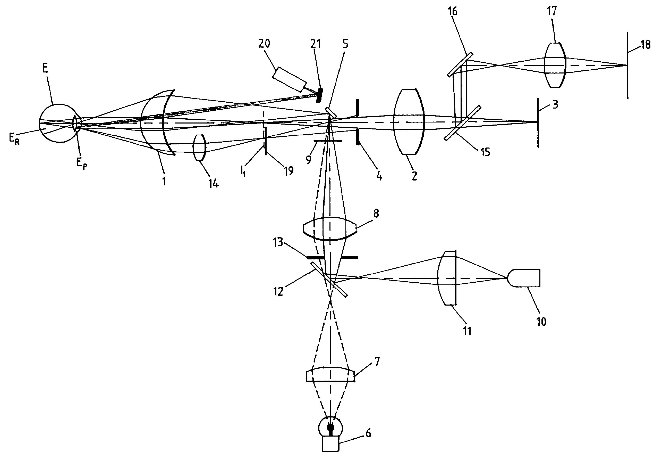
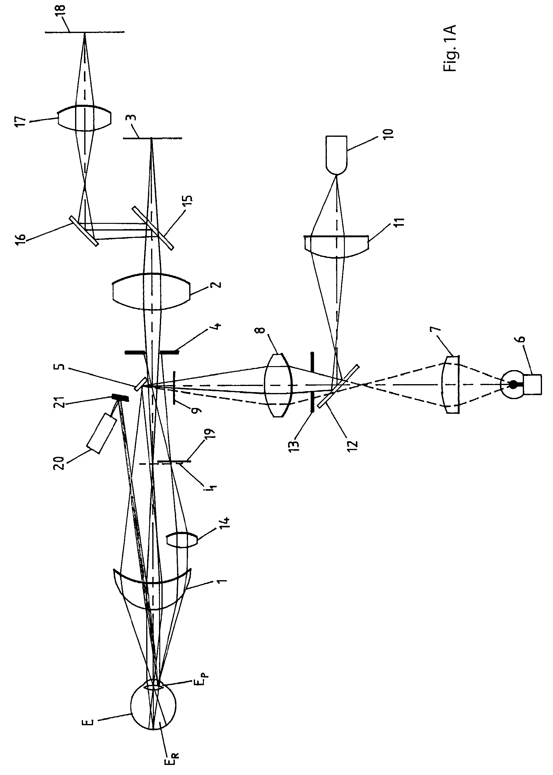
[0044] Referring to FIG. 1A it can be seen that the light source 10 projects light via condenser lens 11, mirror 12, lens 8, mirror 5 through objective lens 1 onto the fundus ER of the subject eye. Stop 13 is conjugate with auxiliary lens 14, such that no light from light source 10 impinges on auxiliary lens 14, thus avoiding unwanted reflections from lens 14 and also from the eye pupil EP and other anterior surfaces of the subject eye after transmission through lens 8.

[0045] Light from source 10 that is reflected from the eye fundus ER passes through objective lens 1, forming a first aerial image i1 and then to photographing lens 2, mirror 15 and 16, and relay lens 17 to the observation camera 18.

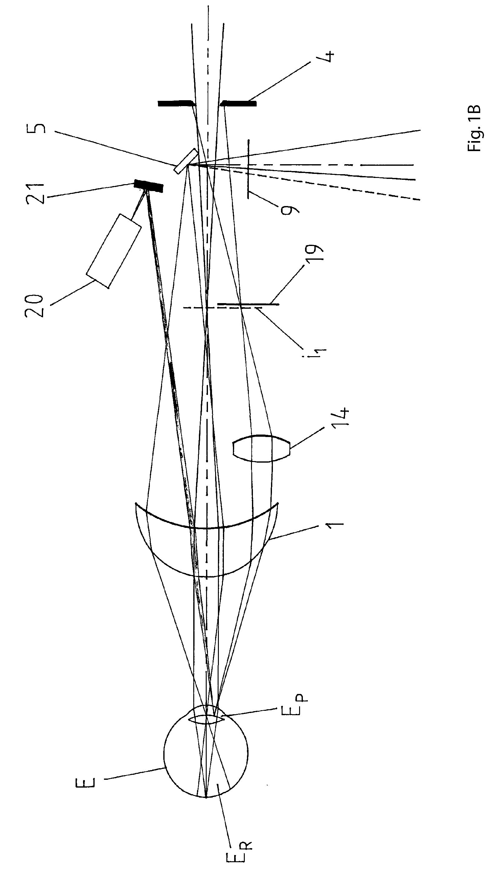
[0046]FIG. 1B shows a close up of FIG. 1A. Concurrently light from one or more alignment targets 20 is projected via mirror 21 through objective 1 and an image of the alignment target is focused onto the iris of the eye pupil EP of subject eye.

[0047] Concurrently light reflected from th...


PUM


Abstract

A fundus camera is provided with auxiliary optical components and a plurality of projected alignment marks, wherein the alignment marks are in focus and coincident on the iris of the eye when the fundus camera is correctly aligned and the auxiliary optical components allow the alignment marks to be observed as an anterior view in focus, replacing part of the view of the eye fundus which is also in focus in the same view. The auxiliary view optical components may be linked to the focus of the observation system and the associated projected focus indicating marks such that all remain in adequate focus to enable the alignment and focus of the fundus camera to be performed satisfactorily.

Description

[0001] This application is a continuation of International Application PCT / AU02 / 01681, with an international filing date of Dec. 13, 2002, published in English under PCT Article 21(2), which is a Paris Convention filing of Australian Application PR 9500 having a priority date of Dec. 13, 2001. International application PCT / AU02 / 01681 and Australian application PR 9500 are hereby incorporated by reference herein.BACKGROUND OF INVENTION [0002] 1. Field of the Invention [0003] This invention relates to improvements in devices for alignment and focusing of a fundus camera. [0004] A fundus camera is used to capture an image of the fundus (posterior portion of the eye, including the retina and blood vessels). This fundus image can be examined by a third party or compared to fundus images taken at an earlier date, to facilitate diagnosis of retinal disease. [0005] The fundus camera comprises an objective lens to form an image of the fundus of the eye, other lenses to form an image on the r...

Claims


Application Information

Patent Timeline
IPC IPC(8): A61B3/12A61B3/14A61B3/15
CPCA61B3/12A61B3/152A61B3/14
Inventor KOENNECKE, GREG
Owner VISION BIOSYST
Why Eureka
Try Eureka