
Wavelength division multiplexed self-healing passive optical network using wavelength injection method

a wavelength injection and wavelength division multiplexing technology, applied in the field of self-healing passive optical networks, can solve the problems of large loss of transmitted data, insufficient introduction of the aforementioned ring network structure,

Active Publication Date: 2005-07-14
SAMSUNG ELECTRONICS CO LTD
View PDF7 Cites 26 Cited by
  • Summary
  • Abstract
  • Description
  • Claims
  • Application Information

AI Technical Summary

Benefits of technology

[0021] The present invention has been made to solve the aforementioned problems occurring in the prior art. An object of the present invention is to provide a wavelength division multiplexed self-healing passive optical network capable of detecting a cut of or deterioration of a feeder fiber or a distribution fiber. It is a further object of the present invention to correct an error due to the cut or deterioration by itself in a passive optical network having a star structure.

Problems solved by technology

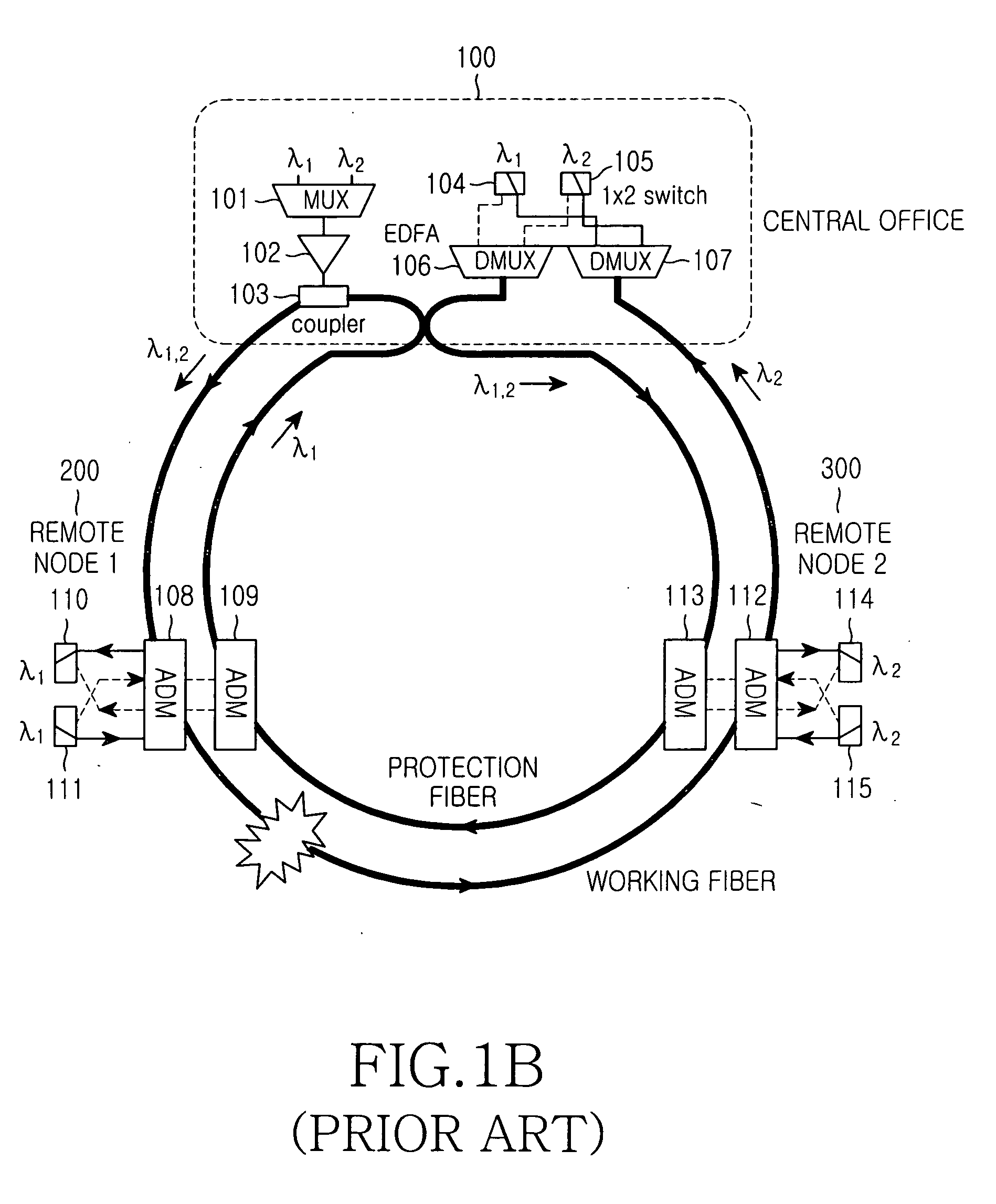
In the WDM-PON as described above, when an unexpected error occurs, such as a cut of a feeder fiber or a distribution fiber, a large quantity of transmitted data may be lost even though the error time period is short.
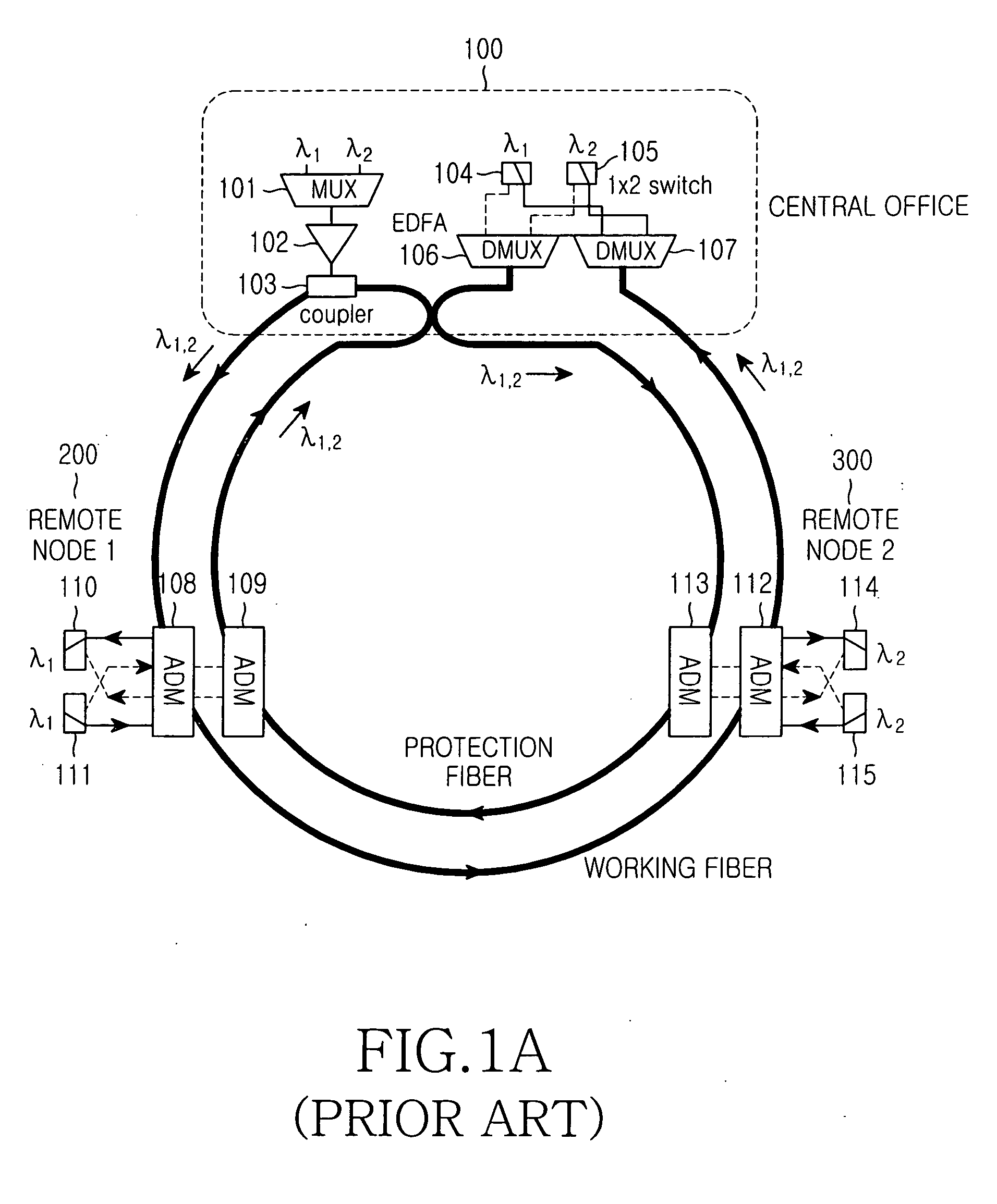
However, it is insufficient to introduce the aforementioned ring network structure to a PON which connects a central office to a remote node and connects the remote node to an optical network unit.

Method used


Image

  • Wavelength division multiplexed self-healing passive optical network using wavelength injection method
  • Wavelength division multiplexed self-healing passive optical network using wavelength injection method
  • Wavelength division multiplexed self-healing passive optical network using wavelength injection method

Examples


Embodiment Construction

[0029] A preferred embodiment according to the present invention will be described below with reference to the accompanying drawings. Detailed description of known functions and configurations incorporated herein will be omitted when it may make the subject matter of the present invention unclear.

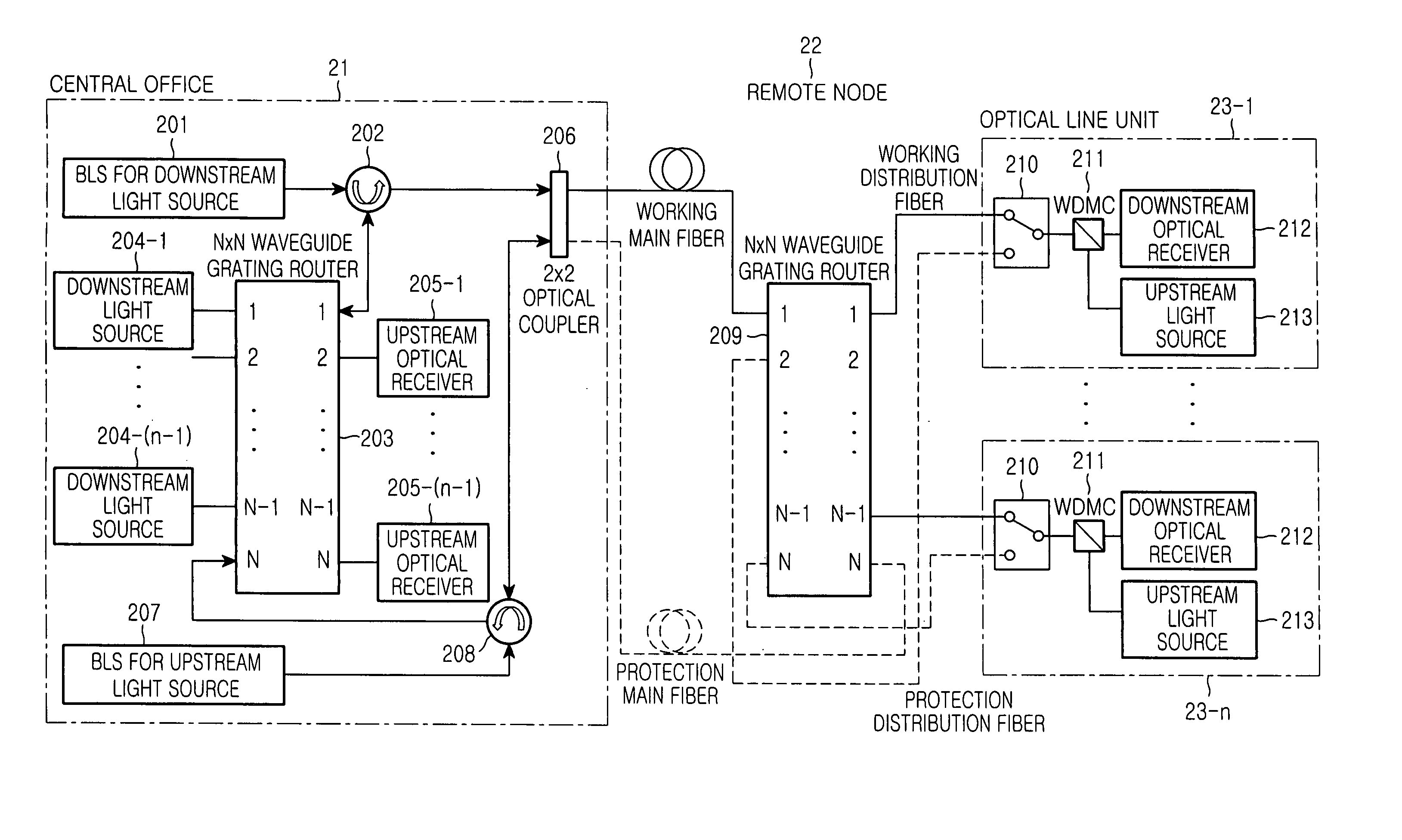
[0030]FIG. 2 is a block diagram of a wavelength division multiplexed self-healing passive optical network using a wavelength injection method according to one embodiment of the present invention.

[0031] As shown in FIG. 2, the wavelength division multiplexed self-healing passive optical network using the wavelength injection method includes a central office 21, one strand of working fiber and one strand of protection fiber connecting the central office 21 to a remote node 22, an N×N multiplexer / demultiplexer (waveguide grating router) 209 located in the remote node 22, working fibers and protection fibers connecting the remote node 22 to optical network units 23-1 to 23-(n-1), and the opti...


PUM


Abstract

A wavelength division multiplexed self-healing passive optical network using a wavelength injection method. The wavelength division multiplexed self-healing passive optical network includes a central office for coupling modulated multiplexing optical signals and broadband optical signals for an upstream light source. These signals are combined into one signal and transmitted to a plurality of optical network units as a coupled signal through a working main fiber and a protection main fiber. The remote node connects to the central office through the working main fiber and the protection main fiber and to the optical network units through working distribution fibers and protection distribution fibers. The remote node demultiplexes the modulated multiplexing optical signals and the broadband optical signals for an upstream light source. The remote node transmits the demultiplexed signals to the optical network units, which receive the modulated optical signals and the broadband optical signals for an upstream light source, which are transmitted from the remote node and correspond to predetermined optical network units, optically demodulate the modulated optical signals, and modulate upstream optical signals by means of the demultiplexed broadband optical signals for an upstream light source.

Description

CLAIM OF PRIORITY [0001] This application claims priority to an application entitled “Wavelength division multiplexed self-healing passive optical network using wavelength injection method,” filed in the Korean Intellectual Property Office on Jan. 9, 2004 and assigned Serial No. 2004-1754, the contents of which are hereby incorporated by reference. BACKGROUND OF THE INVENTION [0002] 1. Field of the Invention [0003] The present invention relates to a self-healing passive optical network capable of detecting and healing cuts or deterioration of a feeder fiber or distribution fiber, thereby restoring the network by itself. [0004] 2. Description of the Related Art [0005] A wavelength division multiplexing passive optical network (WDM-PON) can ensure the secrecy of communication and can easily accommodate special communication services required from each subscriber unit. The WDM-PON can enlarge channel capacity by assigning a specific wavelength to each subscriber unit and communicating ...

Claims


Application Information

Patent Timeline
Patent Type & Authority Applications(United States)
IPC IPC(8): H04L12/437H04B10/03H04B10/032H04B10/07H04B10/079H04B10/272H04J14/00H04J14/02
CPCH04J14/02H04J14/0226H04J14/0227H04J14/025H04J14/029H04J14/0246H04J14/0282G09F23/10B42D15/00B42D5/047
Inventor SHIN, HONG-SEOKJUNG, DAE-KWANG
Owner SAMSUNG ELECTRONICS CO LTD
Learn More