Sample carrier

a sample carrier and sample technology, applied in the field of sample carriers, can solve the problems of increased labor, time, and additional material costs, and the evaporation of aqueous or other solvent-containing sample liquids that are often subject to considerable evaporation, and achieve the effect of reducing labor costs, increasing material costs, and increasing the cost of materials

Inactive Publication Date: 2005-07-14
BOEHRINGER INGELHEIM MICROPARTS
View PDF23 Cites 6 Cited by
  • Summary
  • Abstract
  • Description
  • Claims
  • Application Information

AI Technical Summary

Benefits of technology

[0008] The primary object of this invention is to devise a sample carrier and its use which, even for longer residence time of the sample liquid in the sample carrier, especially for reactions which continue for a long time and / or at high temperatures, can be used without adding sample liquid again, or covering of the sample receiver after the first application of sample liquid.

Problems solved by technology

The frequently aqueous or other solvent-containing sample liquids are subject to considerable evaporation in spite of the covering, especially as a result of the open or opened sample receiver and the required ventilation.
Beyond the associated labor input, there is also the risk here that in the meantime air can flow in or can be sucked in.
But this means additional expenditure of labor, time, and additional material cost.

Method used


Image

  • Sample carrier
  • Sample carrier
  • Sample carrier

Examples


first embodiment

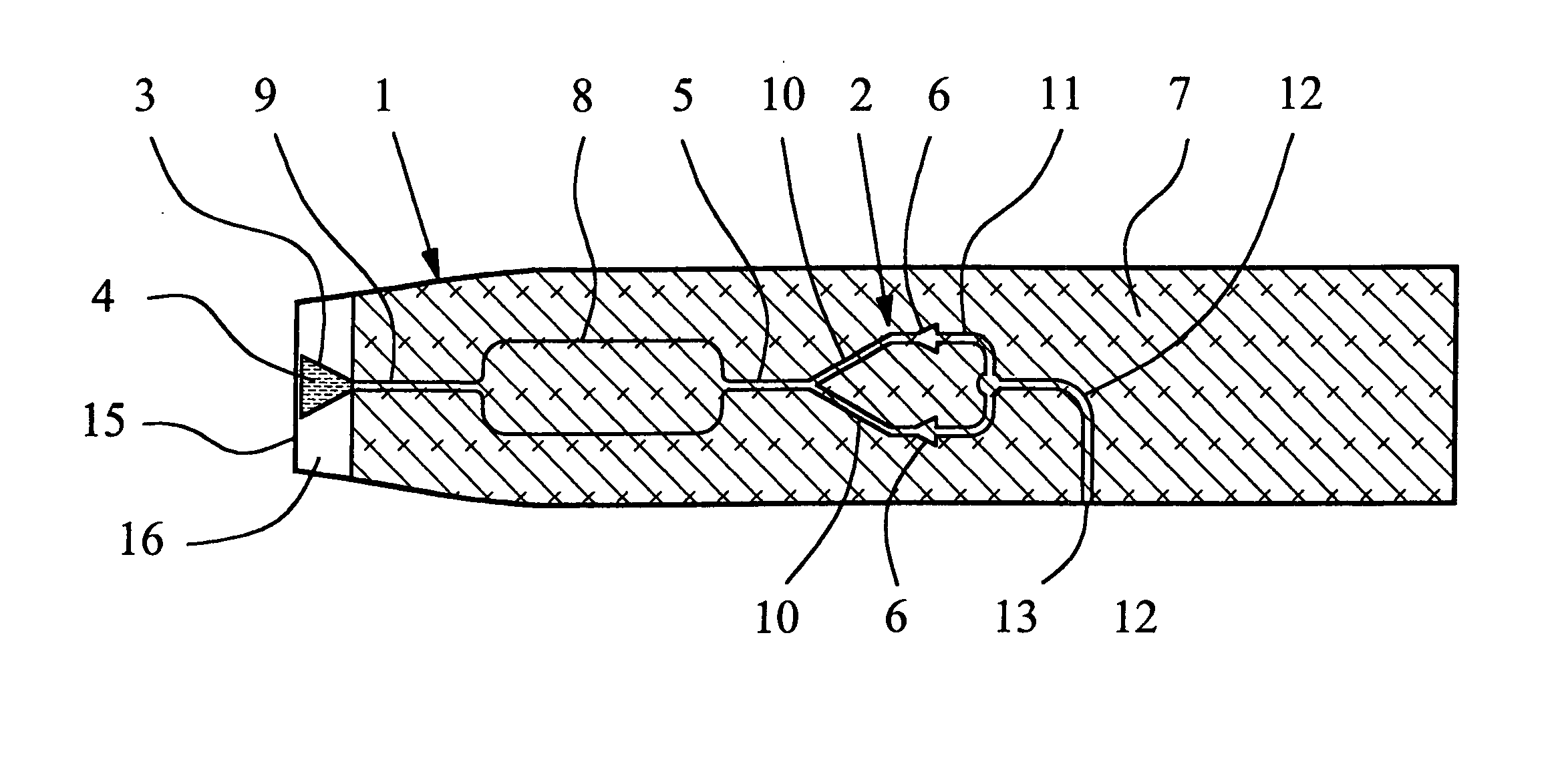
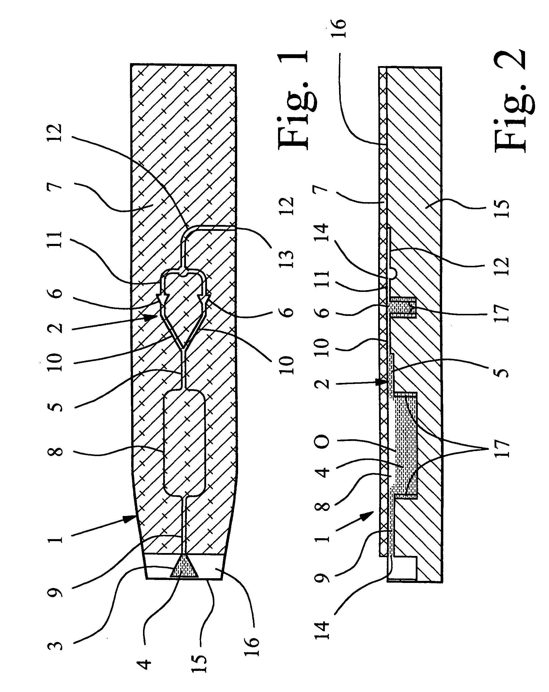
[0025] Preferably all the cavities 2 are formed in the base body 15 of the sample carrier 1. In particular, all cavities 2 are open proceeding from the flat side 16 of the base body 15 and toward the flat side 16, formed for example, by cups, riffles, grooves, recesses or the like. The covering 7 is cemented, laminated or in some other way, applied to the base body 15 and its flat side 16, and covers all cavities 2 of the sample carrier 1, except for the sample receiver 3 in the first embodiment, so that the cavities 2 are also closed to the top, as indicated in FIGS. 1 and 2. In the embodiment, the sample carrier 1 is thus made preferably in two parts. Alternatively, the sample carrier 1 can also be made in one part or can have several coverings 7 which can optionally be applied separately. Instead of the preferred film-like execution of the covering 7, it can also be formed, for example, by a glass plate or other suitable material with suitable properties with suitable shaping.

[00...

third embodiment

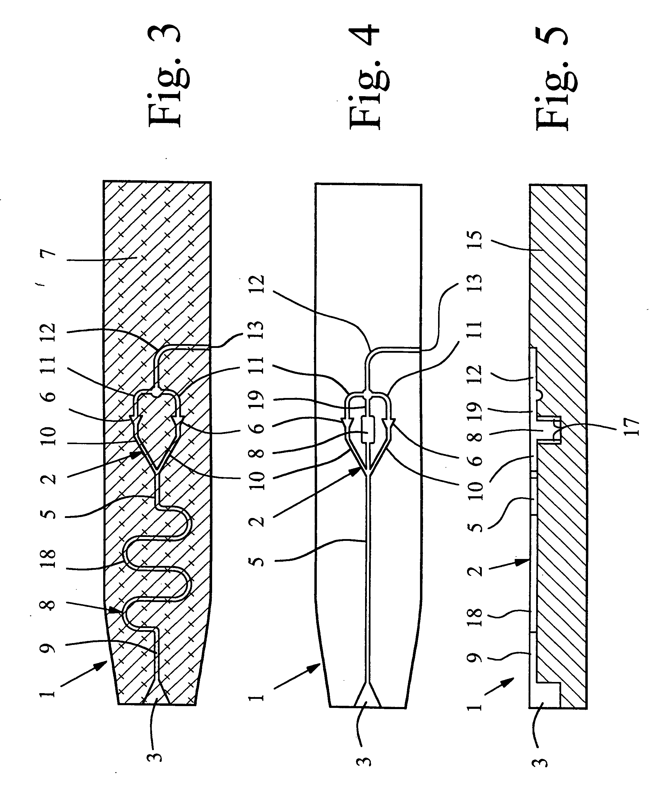
[0043] In FIGS. 4 and 5, the sample liquid 4 and the covering 7 are omitted for the sake of simplification, FIG. 4 showing an overhead view which corresponds to FIGS. 1 and 3. FIG. 4 shows the sample carrier 1. The reservoir 8 is connected to the distribution channel 5 parallel to the sample chambers 6. In particular, the reservoir 8, after or with the sample chambers 6 and their feed channels 10, is connected to the latter on the end of the distribution channel 5 so that the reservoir 8 can be filled with sample liquid 4 after the sample chambers 6, in order to first allow rapid filling of the sample chambers 6 with sample liquid 4.

[0044] In the third embodiment, the reservoir 8 is made preferably in the manner of a cup or chamber. In addition, the reservoir 8 is connected to the ventilation collecting channel 12 for ventilation and aeration via another connecting channel 19. Preferably between this other connecting channel 19 and the reservoir 8 or the ventilation collecting chann...


PUM

PropertyMeasurementUnit
holding volumesaaaaaaaaaa
relative atmospheric humidityaaaaaaaaaa
temperatureaaaaaaaaaa

Abstract

A sample carrier with a sample receiver for the sample liquid and with preferably several sample chambers which are connected thereto is proposed. In order to avoid refilling with sample liquid when it evaporates or is otherwise lost or used up, there is additionally a reservoir for sample liquid which is covered in the same way as the sample chambers and which has a connecting channel to the environment which can be closed by the sample liquid.

Description

BACKGROUND OF THE INVENTION [0001] 1. Field of Invention [0002] This invention relates to a sample carrier having sample chambers for receiving samples for analysis. [0003] 2. Description of Related Art [0004] In a sample carrier known from practice, the sample chambers are made in a base plate on one side, therefore they are open towards the flat side. After filling with reagents, the sample chambers are covered by a film. For chemical or biological diagnostics, a sample receiver is filled with a sample liquid by means of a pipette or the sample liquid is aspirated, for example, by capillary forces. The sample liquid then flows automatically as a result of capillary forces via a distribution channel and feed channels into the sample chambers. In the sample chambers, the sample liquid reacts with the reagents which have been added beforehand. The reactions are detected, for example, optically. [0005] The reactions which proceed in the sample chambers often last several hours and are...

Claims


Application Information

Patent Timeline
Patent Type & Authority Applications(United States)
IPC IPC(8): B01L3/00G01N1/00G01N37/00
CPCB01L3/502723B01L3/502738B01L2200/026B01L2400/0688B01L2300/0825B01L2300/087B01L2400/0406B01L2200/142
Inventor OSTERLOH, DIRKPETERS, RALF-PETER
Owner BOEHRINGER INGELHEIM MICROPARTS
Why Eureka
Try Eureka