Antenna device and mobile communication terminal equipped with antenna device

a mobile communication terminal and antenna technology, applied in the direction of resonant antennas, elongated active elements, substation equipment, etc., can solve the problems of increased power supply loss, difficulty in principle in setting the impedance value of the balance power supply type antenna, and inability to adjust the impedance value of the balance-imbalance converter. , to achieve the effect of simple construction

Active Publication Date: 2005-07-14
TOSHIBA CLIENT SOLUTIONS CO LTD
View PDF9 Cites 73 Cited by
  • Summary
  • Abstract
  • Description
  • Claims
  • Application Information

AI Technical Summary

Benefits of technology

[0014] An object of the present invention is to provide an antenna device that can be used under a plurality of frequencies ...

Problems solved by technology

However, it is difficult in principle to set appropriately the impedance value of the balance power supply type antenna.
In addition, a balance-imbalance converter is required in the case of supplying an electric power from the substrate.
It follows that the balance power supply type antenna gives rise to another problem that the power supply loss is increased.
Also, the balance power supply type antenna is disadvantageous over, for example, the dipole type antenna in respect of the antenna gain.
Such being the situation, the balance power supply type antenna fails to provide a suitable means for overcoming the above-noted difficulty inherent in the built-in type antenna.
Therefore, a problem resides in the folding dipole antenna that it is difficult to allow the mobile communication terminal to be used under a plurality of freque...

Method used


Image

  • Antenna device and mobile communication terminal equipped with antenna device
  • Antenna device and mobile communication terminal equipped with antenna device
  • Antenna device and mobile communication terminal equipped with antenna device

Examples


first embodiment

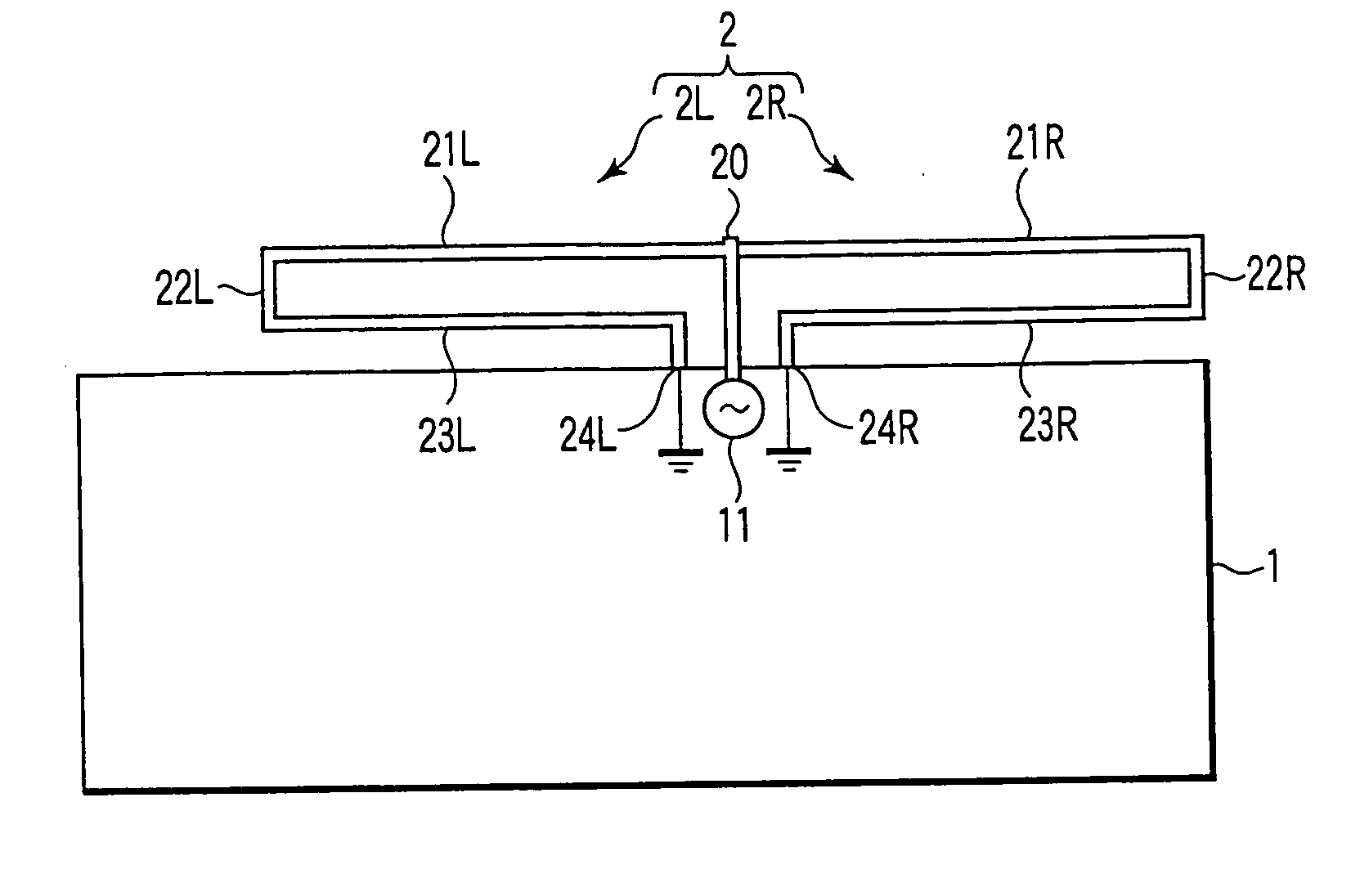
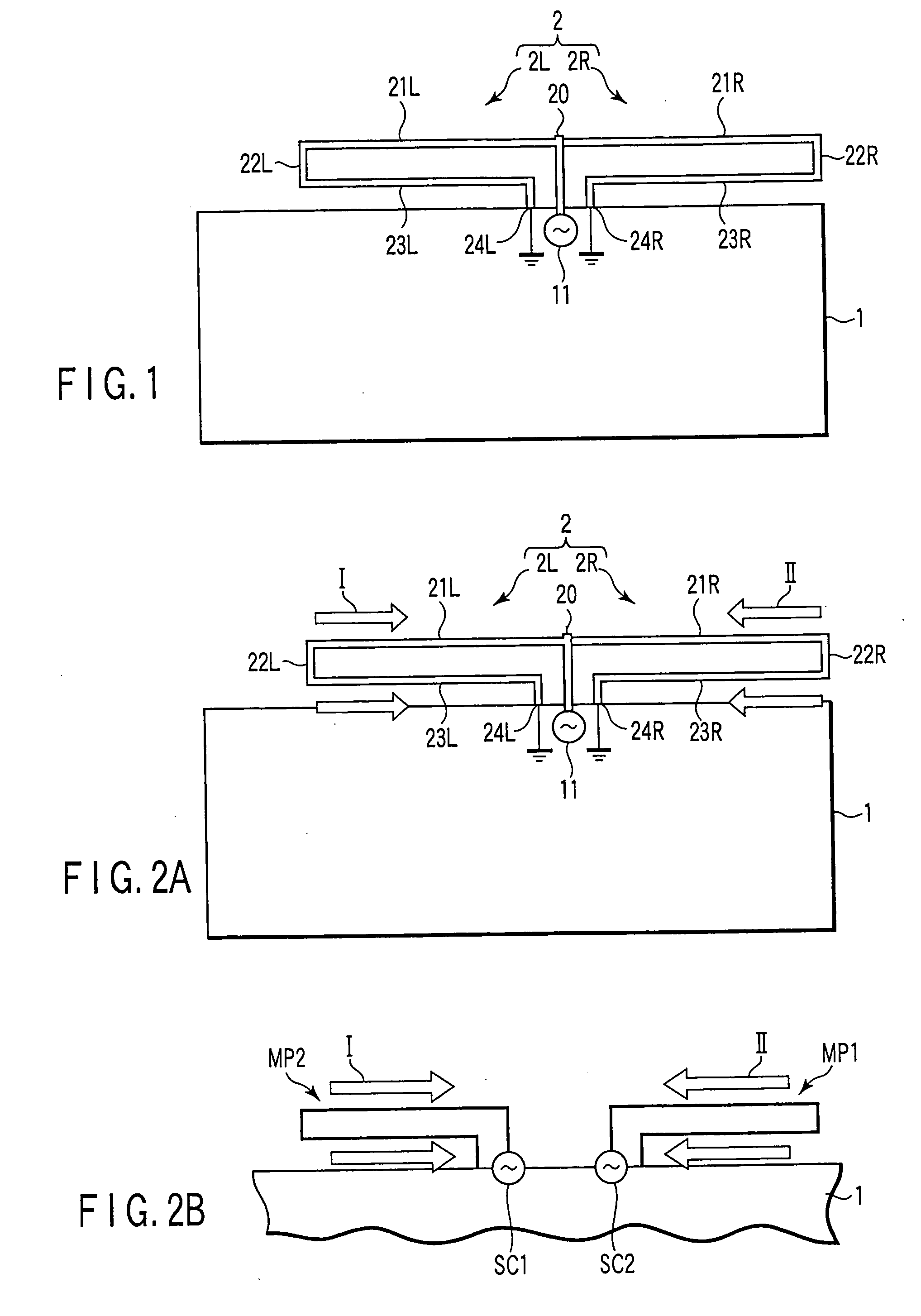
[0038]FIG. 1 shows the substrate of a mobile communication terminal according to the present invention and the construction of the antenna device mounted to the substrate.

[0039] As shown in FIG. 1, a substrate 1 is housed in the casing of a mobile communication terminal (not shown). Also, an antenna device 2 mounted to the substrate 1 is housed similarly in the mobile communication terminal. A power supply section 11 capable of a power supply is mounted to the substrate 1 so as to permit an electric power to be supplied from the power supply section 11 into the antenna device 2 shown in FIG. 1. Also, the antenna device 2 includes a branching point 20 for branching the current.

[0040] The antenna device 2 comprises a folding monopole antenna 2L and an additional antenna 2R. The folding monopole antenna 2L includes a forward path section 21L formed of a conductive line extending from a starting point connected to the power supply point 11 (the starting point substantially correspondin...

second embodiment

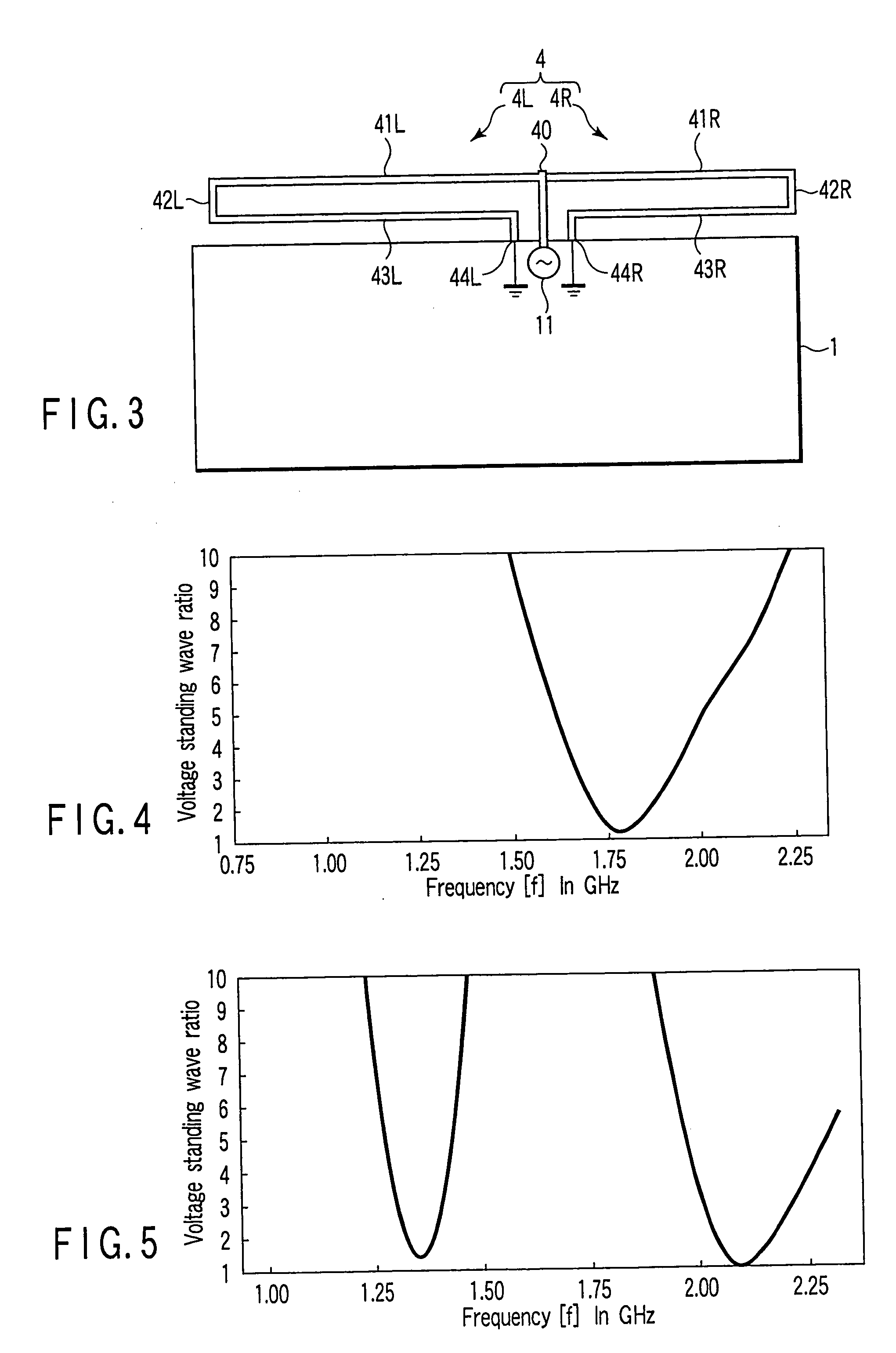
[0049]FIG. 3 shows the substrate 1 of a mobile communication terminal according to the present invention and an antenna device 4 mounted to the substrate. A power supply section 11 capable of a balance power supply is mounted to the substrate 1 as shown in FIG. 3 so as to permit an electric power to be supplied from the power supply section 11 to the antenna device 4. The antenna device 4 comprises a folding monopole antenna 4L and an additional antenna 4R like the antenna device shown in FIG. 1. The antenna device 4 includes a branching point 40 for branching the current supplied from the power supply section 11.

[0050] As shown in FIG. 3, the folding monopole antenna 4L comprises a forward path section 41L including a conductive portion extending from the power supply section 11 to reach the branching point 40, a folding section 42L, and a backward path section 43L. The backward path section 43L is connected to the ground point 44L connected to the ground point of the substrate 1. ...

third embodiment

[0057]FIG. 6A shows a mobile communication terminal according to the present invention. As shown in the drawing, a folding monopole antenna 5L is mounted to the substrate 1 shown in FIG. 6A. In this case, the forward path section 51L of the folding monopole antenna 5L linearly extends from a folding section 52L to a terminal point 55L. To be more specific, the antenna structure shown in FIG. 6A comprises an L-shaped forward path section 51L, a folding section 52L extending from the forward path section 51L, and a backward path section 53L extending from the folding section 52L in a manner to form an L-shape and having the terminal point connected to the substrate 1 in the ground point 54L. In other words, the antenna structure shown in FIG. 6A comprises an L-shaped portion 51L-1 in which the forward path section 51L extends to reach the folding section 52L, and a linear extending section 51L-2 extending linearly outward from the folding section 52L. It should be noted that the free ...


PUM


Abstract

In an antenna device, a half wavelength dipole antenna is folded so as to form a forward path section, a folding section and a backward path section such that the backward path section is connected to the substrate at the ground terminal, and an electric power is supplied from the power supply source at the branching point, so as to configure a folding monopole antenna. Also, an additional antenna is folded similarly and connected to the monopole antenna such that the branching point and the power supply section are shared by the monopole antenna and the additional antenna.

Description

CROSS-REFERENCE TO RELATED APPLICATIONS [0001] This application is based upon and claims the benefit of priority from prior Japanese Patent Application No. 2004-005751, filed Jan. 13, 2004, the entire contents of which are incorporated herein by reference. BACKGROUND OF THE INVENTION [0002] 1. Field of the Invention [0003] The present invention relates to an antenna device and a mobile communication terminal equipped with an antenna device, particularly, to an antenna device housed in the casing of a mobile communication terminal and to the mobile communication terminal equipped with the antenna device. [0004] 2. Description of the Related Art [0005] The antenna for a mobile communication terminal is being changed from the type resembling the whip type antenna, which formed a main stream in the past and which is mounted to the communication apparatus such that the antenna can be withdrawn to the outside of the casing of the communication apparatus, to a built-in type antenna. The bu...

Claims


Application Information

Patent Timeline
IPC IPC(8): H01Q1/24H01Q5/10H01Q5/364H01Q5/371H01Q5/378H01Q7/00H01Q9/42
CPCH01Q1/243H01Q7/00H01Q5/378H01Q5/371H01Q9/42
Inventor SATO, KOICHIAMANO, TAKASHI
Owner TOSHIBA CLIENT SOLUTIONS CO LTD
Why Eureka
Try Eureka