Ultrasound diagnostic apparatus
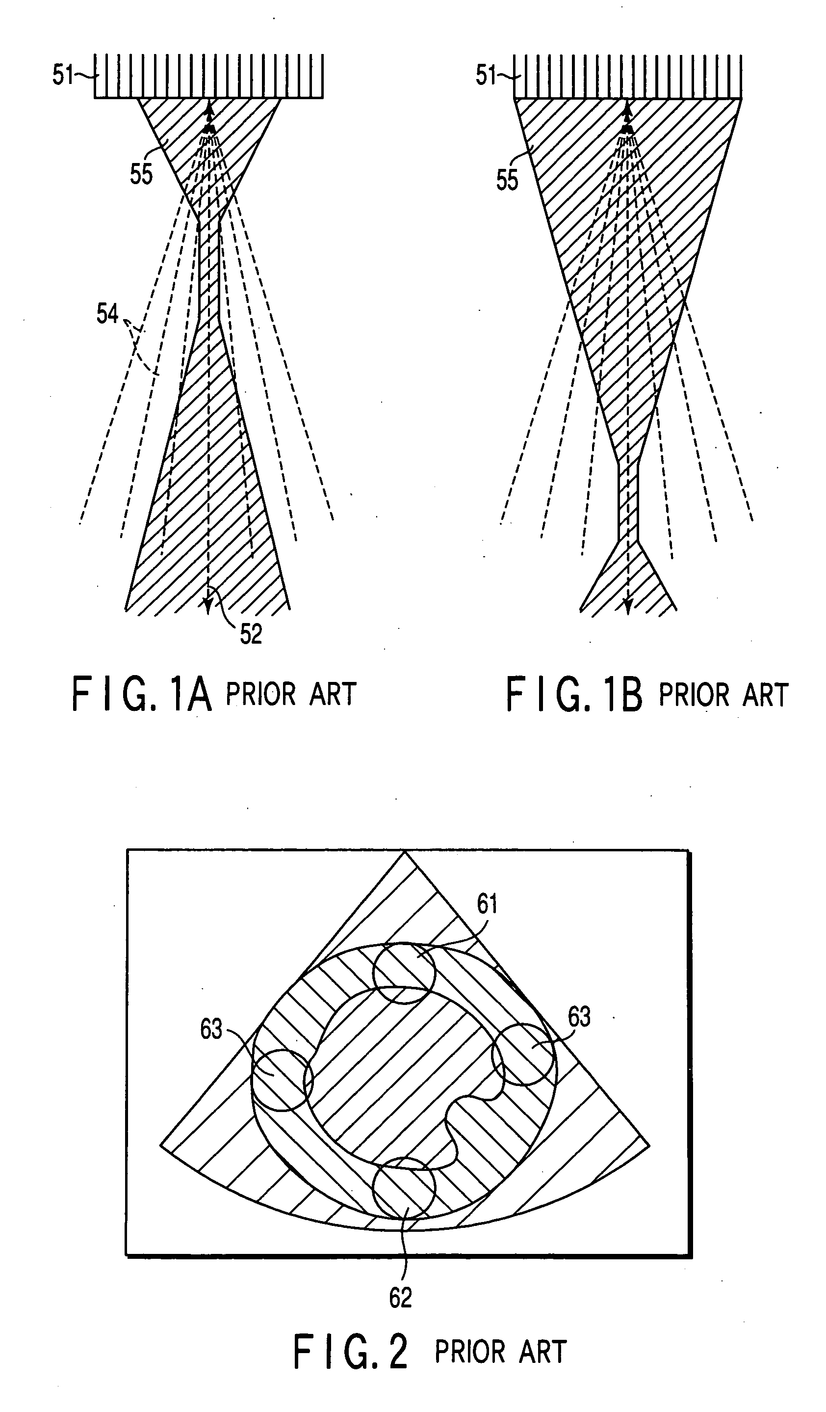
a diagnostic apparatus and ultrasonic technology, applied in the field of ultrasonic diagnostic apparatus, can solve the problems of contrast agent instantaneously collapsing upon application of ultrasound waves, microbubbles on adjacent scanning lines rapidly shrinking and collapsing,
- Summary
- Abstract
- Description
- Claims
- Application Information
AI Technical Summary
Benefits of technology
Problems solved by technology
Method used
Image
Examples
first embodiment
(Arrangement and Flow of Signals)
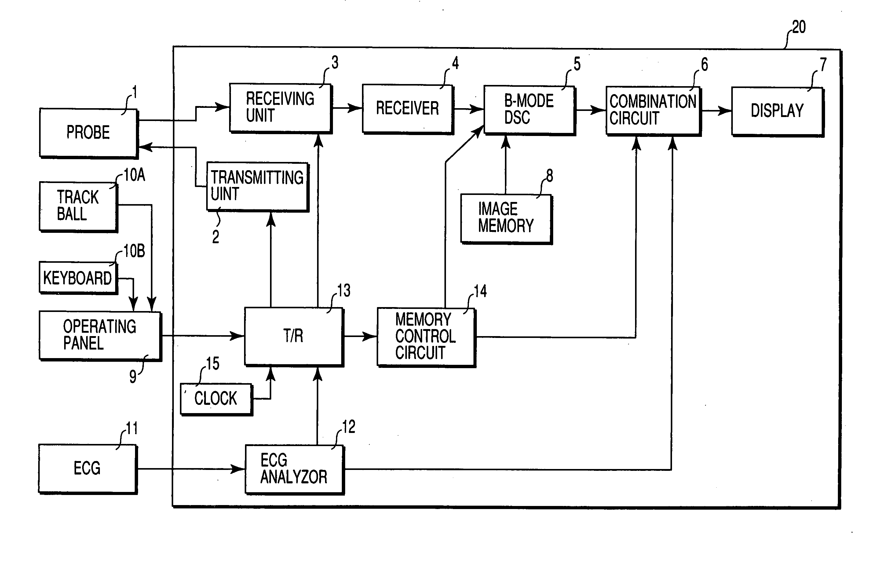
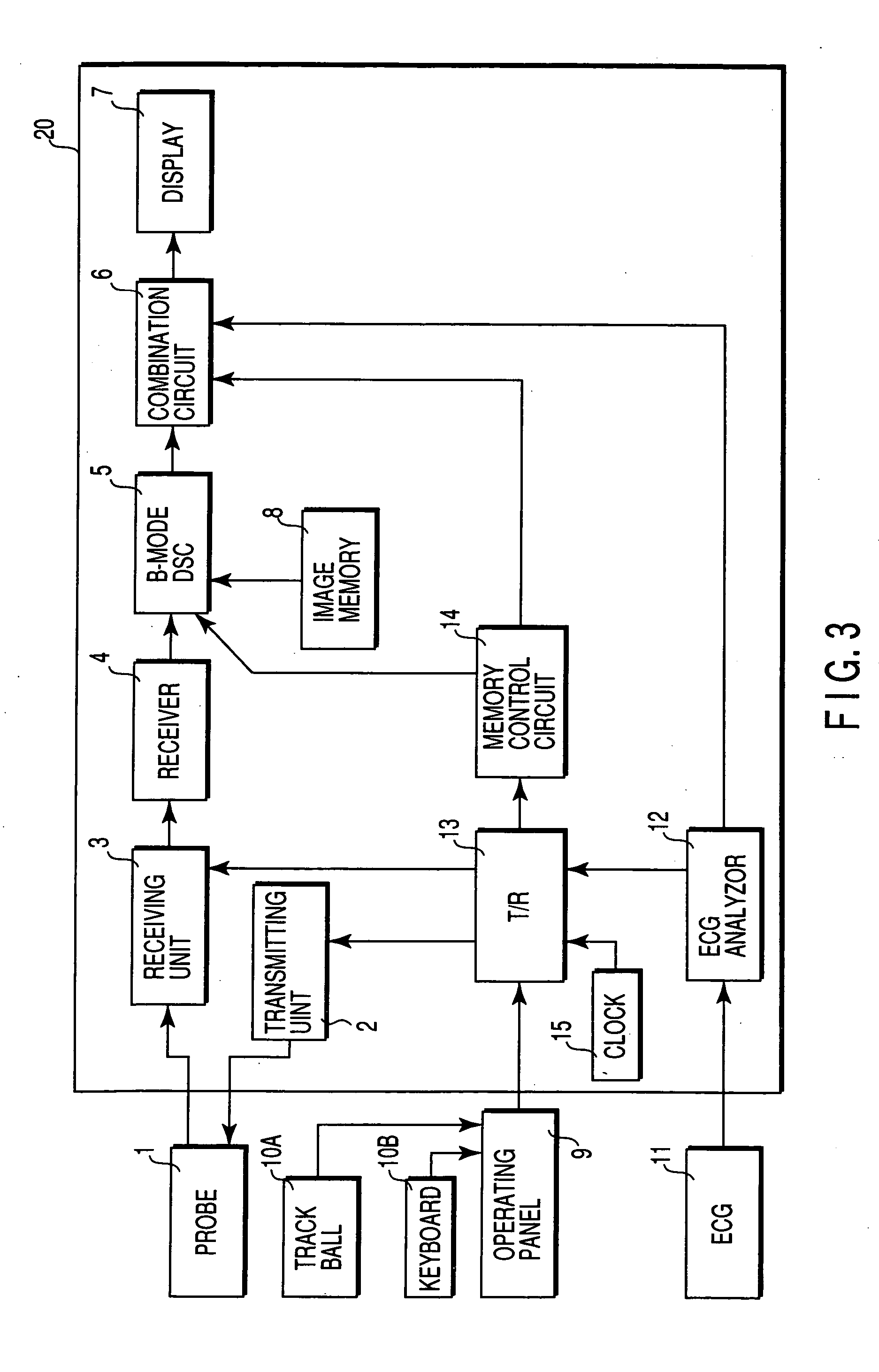
[0047]FIG. 3 shows the arrangement of an ultrasound diagnostic apparatus according to the first embodiment. An ultrasound probe 1 is connected to an apparatus body 20. The apparatus body 20 scans the inside of an object to be examined by using an ultrasound beam through the ultrasound probe 1, creates tomographic image data by processing the obtained reception signal, and displays the image. An operating panel 9 having a trackball 10A, keyboard 10B, and the like is connected to the apparatus body 20. Various operator instructions such as an instruction to set a region of interest (ROI) are input to the apparatus body 20 through the operating panel 9.
[0048] A plurality of electroacoustic conversion elements (transducers) are arrayed on the distal end portion of the ultrasound probe 1. One or a few adjacent transducers constitute one channel. RF voltage pulses are applied from a transmitting unit 2 of the apparatus body 20 to the transducers. The tr...
second embodiment
[0085] The second embodiment provides a partial imaging method. The partial imaging method is a method of segmenting a scan plane into a plurality of local portions and scanning each local portion in an optimal scan operation sequence, instead of sequentially moving over scanning lines within the scan plane, thereby obtaining optimal (maximum) contrast on the entire scan plane and combining the resultant data into a one frame.
(Arrangement and Flow of Signals).
[0086]FIG. 9 is a block diagram showing an ultrasound diagnosis apparatus of this embodiment. The same reference numerals as in the first embodiment denote the same parts in the first embodiment, and a detailed description thereof will be omitted. A template memory 21 stores pieces of information about a plurality of models for segmenting a scan slice into a plurality of local regions (partial regions). One optimal pattern for a sliceal shape of a portion to be diagnosed is read out from the template memory 21 in accordance ...
third embodiment
[0103]FIG. 18 shows the arrangement of the third embodiment. A transmission / reception control circuit 13 controls the timing of pulses from a transmitting unit. This embodiment performs intermittent transmission using a timing signal from an ECG analyzer 12 or clock 15 in accordance with a mode switching instruction sent from an operating panel 9. Intermittent transmission is transmission in which frame generation intervals are sufficiently larger than those in normal continuous transmission (20 to 100 frames / sec). For example, time intervals corresponding to four or five heartbeats are input.
[0104] The transmission / reception control circuit 13 instructs a transmitting unit 2 to perform transmission of a plurality of frames per trigger (in other words, continuous scanning in a short period of time). FIG. 19 shows a conceptual rendering of this transmission. Referring to FIG. 19, five frames are continuously transmitted / received at predetermined time intervals (sufficiently longer t...
PUM
 Abstract
Description
Claims
Application Information
 - R&D
- Intellectual Property
- Life Sciences
- Materials
- Tech Scout
- Unparalleled Data Quality
- Higher Quality Content
- 60% Fewer Hallucinations
Browse by: Latest US Patents, China's latest patents, Technical Efficacy Thesaurus, Application Domain, Technology Topic, Popular Technical Reports.
© 2025 PatSnap. All rights reserved.Legal|Privacy policy|Modern Slavery Act Transparency Statement|Sitemap|About US| Contact US: help@patsnap.com


