Stabilization device for bones comprising a spring element and manufacturing method for said spring element

a stabilization device and spring element technology, applied in the field of stabilization devices for bones, can solve the problems of rigid systems that do not permit any movement, do not allow for the mutual stabilization of bone parts and controlled partial motion, and fixation between bone screws and springs to loosen, etc., and achieve suitable elastic properties and easy implementation

Active Publication Date: 2005-07-14
BIEDERMANN TECH GMBH & CO KG
View PDF30 Cites 701 Cited by
  • Summary
  • Abstract
  • Description
  • Claims
  • Application Information

AI Technical Summary

Benefits of technology

[0055] The invention is advantageous in that its elastic section allows the bone anchoring element to receive axial forces acting in the direction of the bone anchoring element's shaft axis, as well as flexural forces and torsional forces. This allows for the motion of the bone part or vertebra in which the bone anchoring element is anchored with the motion being limited by the retroactive force. The elastic properties of the of the flexible section of the bone anchoring element are easy to implement during the production of the bone anchoring element by changing the dimensions of the flexible section. The bone anchoring element can be connected to the known connecting elements, such as plates and rods. Thus, it is possible to provide a dynamic stabilization device with a desired limitation of motion by selecting bone anchoring elements with suitable elastic properties and using these in combination with conventional plates or rods.
[0056] The invention also provides methods for stabilization of bones or vertebrae using the stabilization devices described herein. Thus, in a patient in need of bone or vertebrae stabilization, at least two bone anchoring elements are inserted into bone on opposite sides of a fracture, or break, or other instability, or on two adjacent vertebrae. At least one of the bone anchoring elements comprises a bone anchoring section to be anchored in the bone and flexible section as described herein. The connecting element used to connect the bone anchoring elements thereby providing stabilization with a predetermined limited movement.

Problems solved by technology

Such rigid systems do not permit any movement of the bone parts or vertebrae because they are fixed relative to each other.
However, the described solution does not allow for the mutual stabilization of bone parts and controlled partial motion.
This, however, poses the risk that the spring, owing to its flexibility, evades the pressure of the clamping screw, thus causing the fixation between the bone screw and the spring to loosen.
A further disadvantage of the device is that the elasticity of the spring, with otherwise identical spring characteristics, depends on the length of the spring.
However, a stabilization device of this type fails to provide for stabilization against torsion.
Owing to its complex and voluminous structure, this known joint fixation apparatus is not suitable for internal use on the spinal column or other bones.
However, none of these screws are connected with each other via a connecting member.

Method used


Image

  • Stabilization device for bones comprising a spring element and manufacturing method for said spring element
  • Stabilization device for bones comprising a spring element and manufacturing method for said spring element
  • Stabilization device for bones comprising a spring element and manufacturing method for said spring element

Examples


Embodiment Construction

[0090] The invention and various embodiments thereof are presented in FIGS. 1 through 22 and the accompanying descriptions wherein like numbered items are identical. As used herein, the terms flexible element, flexible section, spring like element, elastic element or elastic section refer to an element or section of an element that can have spring-like elastic or flexible properties.

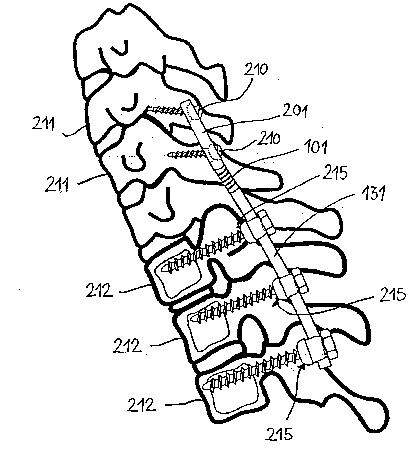
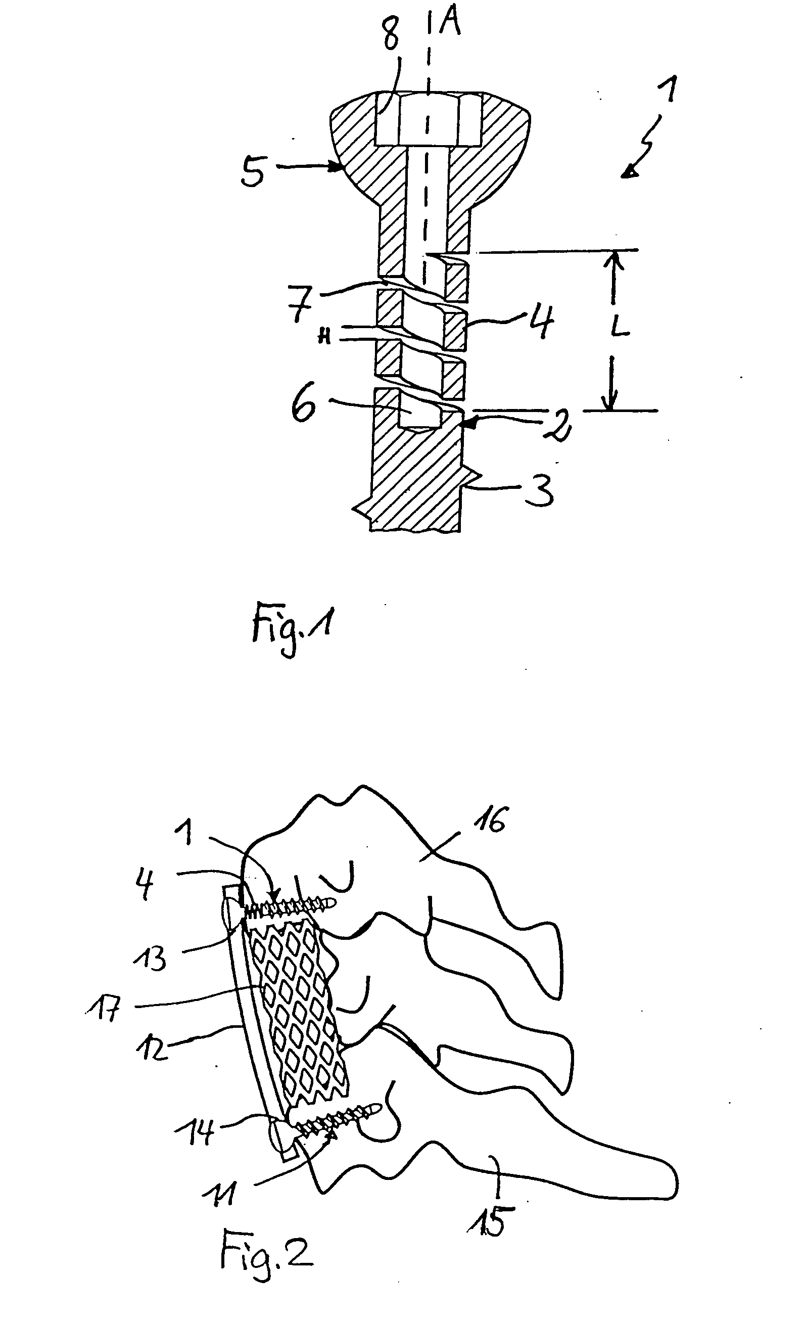
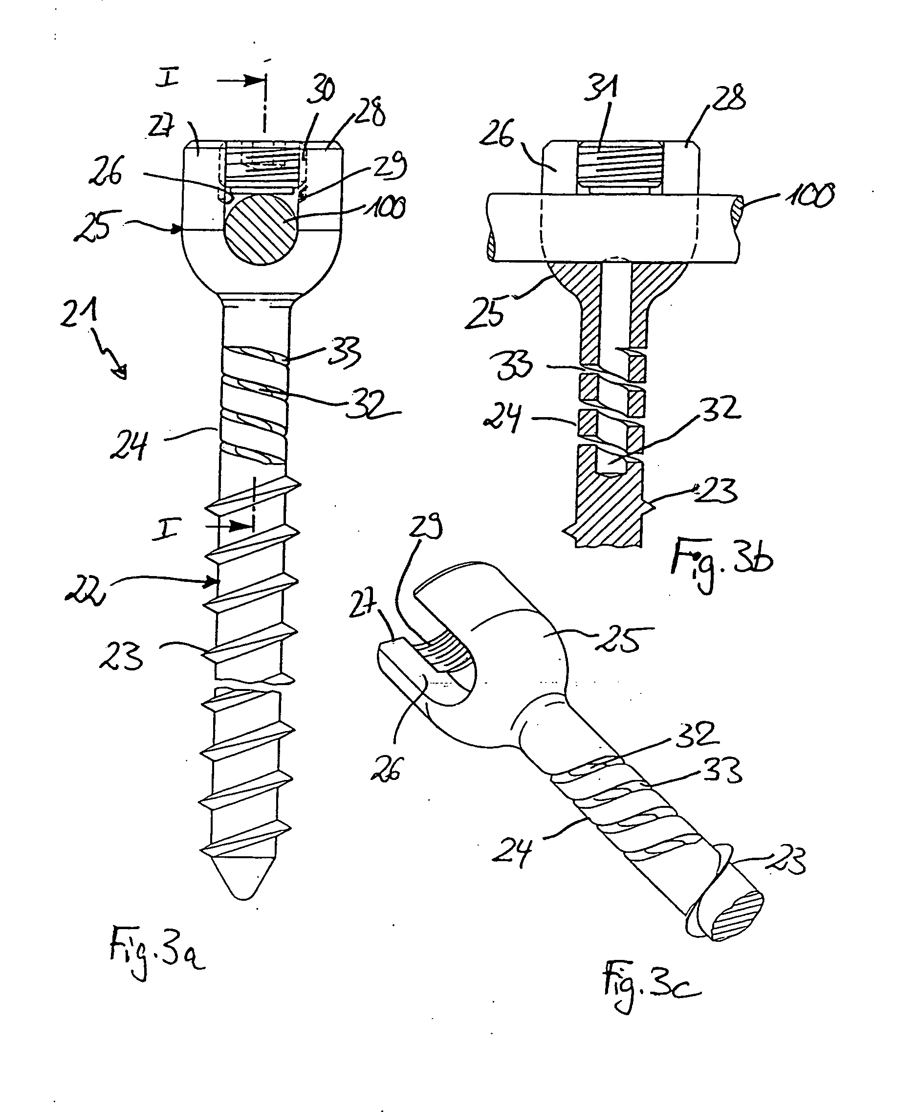
[0091] Bone stabilization devices in accord with the present invention can be designed and implemented in a wide variety of ways. Typically, they will comprise two or more bone anchoring elements and a connecting element connecting at least two bone anchoring elements. At least one of the bone anchoring elements comprises an essentially cylindrical body segment having at one end a threaded portion for anchoring into bone tissue and further comprising a length of a flexible section having a helical slotted opening (or recess) in the outer surface of the cylindrical body, the slot extending radially inwar...


PUM


Abstract

An elastic or flexible element for use in a stabilization device for bones or vertebrae is provided. The elastic or flexible element is provided in the form of an essentially cylindrical body with a first end and a second end opposite thereto, wherein at least one of the opposite ends of the cylindrical body comprises a coaxial bore hole with an internal thread for connecting to a shaft and/or a head of a bone screw or for connecting to a rod section. The present invention further provides a bone anchoring element, e.g. a bone screw, with a shaft for the anchoring in a bone, whereby the shaft comprises an elastic or flexible section which is formed integrally with the shaft or as a separate elastic or flexible element. It is preferable for the elastic section to be implemented in the form of a helical spring. Moreover, the present invention provides a stabilization device for bones, for instance for vertebrae, said device comprising at least one bone anchoring element according to the invention, a second bone anchoring element and a rod or plate connecting the bone anchoring elements.

Description

CROSS REFERENCE TO RELATED APPLICATIONS [0001] This application claims the benefit of priority, and incorporates by reference in their entirety, from U.S. Provisional Application Ser. No. 60 / 518,469 filed Nov. 7, 2003, from U.S. Provisional Application Ser. No. 60 / 523,946 filed Nov. 21, 2003 and from U.S. Provisional Application Ser. No. 60 / 550,182 filed Mar. 3, 2004.FIELD OF THE INVENTION [0002] The present invention relates to a stabilization device for bones comprising a plurality of bone anchoring elements and a connector connecting the bone anchoring elements, the stabilization device being particularly useful for application in spinal surgery or trauma surgery. At least one bone anchoring element comprises a flexible rod-shaped element and a manufacturing method for bone anchoring elements of this type. BACKGROUND OF THE INVENTION [0003] Fixation and stabilization devices are known for the fixation of bone fractures or for the stabilization of the spinal column, which consist ...

Claims


Application Information

Patent Timeline
Patent Type & Authority Applications(United States)
IPC IPC(8): A61B17/00A61B17/56A61B17/60A61B17/64A61B17/70A61B17/86
CPCA61B17/645A61B17/7035A61B17/7028A61B17/7032A61B17/7037A61B17/7041A61B17/705A61B17/7059A61B17/8625A61B17/8635A61B17/8685A61B17/869A61B2017/00526A61B2017/606A61B17/7001A61B17/7004
Inventor BIEDERMANN, LUTZMATTHIS, WILFRIEDHARMS, JURGEN
Owner BIEDERMANN TECH GMBH & CO KG
Why Eureka
Try Eureka